
User manual


...the world's most energy friendly microcontrollers
2012-04-24 - Giant Gecko Family - d0053_Rev0.96 7
www.energymicro.com
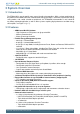
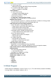
Figure 3.1. Diagram of EFM32GG
Clock Management Energy Management
Serial Interfaces
I/O Ports
Core and Memory
Timers and Triggers
Analog Interfaces Security
32-bit bus
Peripheral Reflex System
ARM Cortex™-M3 processor
Flash
Program
Mem ory
LESENSE
High Freq.
RC
Oscillator
High Freq.
Crystal
Oscillator
Timer/
Counter
Low Energy
Timer
Pulse
Counter
Real Time
Counter
Low Freq.
Crystal
Oscillator
Low Freq.
RC
Oscillator
Watchdog
Timer
RAM
Mem ory
Ext. Bus
Interface
General
Purpose
I/O
Mem ory
Protection
Unit
DMA
Controller
Debug
Interface
w/ ETM
External
Interrupts
Pin
Reset
Hardware
AES
Giant Gecko
LCD
Controller
ADC
DAC
Pulse
Counter
Operational
Am plifier
USB
USART
Low
Energy
UART
I
2
C
UART
Power-on
Reset
Voltage
Regulator
Back-up
Power
Domain
Voltage
Comparator
Brown-out
Detector
TFT
Driver
Back-up
RTC
Pin
Wakeup
Ultra Low Freq.
RC
Oscillator
Note
In the block diagram, color indicates availability in different energy modes.
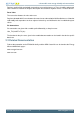
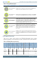
Figure 3.2. Energy Mode indicator
0
1 2 3 4
Note
In the energy mode indicator, the number n indicates Energy Mode n.
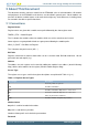
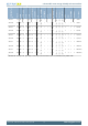
3.4 Energy Modes
There are five different Energy Modes (EM0-EM4) in the EFM32GG, see Table 3.1 (p. 8) . The
EFM32GG is designed to achieve a high degree of autonomous operation in low energy modes. The
intelligent combination of peripherals, RAM with data retention, DMA, low-power oscillators and short
wake-up times, makes it attractive to remain in low energy modes for long periods and thus saving
energy consumption.
Tip
Throughout this document, the first figure in every module description contains an Energy Mode
Indicator that shows in which energy mode(s) the module can operate (see Table 3.1 (p. 8) ).