
User manual

...the world's most energy friendly microcontrollers
2012-04-24 - Giant Gecko Family - d0053_Rev0.96 687
www.energymicro.com
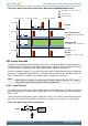
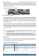
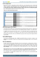
activating (see Figure 28.6 (p. 687) ). The single sample will then follow immediately after the scan
sequence. In this way, the scan sequence will always start immediately when triggered, if the period
between the scan triggers is big enough to allow any single samples that might be triggered to finish
in between the scan sequences.
Figure 28.6. ADC Conversion Tailgating
SINGLESTART
SCANSTART
SCANACT
ADC action
SINGLEACT
Scan Single Scan Single Scan
28.3.7.4 Conversion Trigger
The conversion modes can be activated by writing a 1 to the SINGLESTART or SCANSTART bit
in the ADCn_CMD register. The conversions can be stopped by writing a 1 to the SINGLESTOP or
SCANSTOP bit in the ADCn_CMD register. A START command will have priority over a stop command.
When the ADC is stopped in the middle of a conversion, the result buffer is cleared. The SINGLEACT
and SCANACT bits in ADCn_STATUS are set high when the modes are actively converting or have
pending conversions.
It is also possible to trigger conversions from PRS signals. The system requires one HFPERCLK
cycle pulses to trigger conversions. Setting PRSEN in ADCn_SINGLECTRL/ADCn_SCANCTRL
enables triggering from PRS input. Which PRS channel to listen to is defined by PRSSEL in
ADCn_SINGLECTRL/ADCn_SCANCTRL. When PRS trigger is selected, it is still possible to trigger the
conversion from software. The reader is referred to the PRS datasheet for more information on how to
set up the PRS channels.
Note
The conversion settings should not be changed while the ADC is running as this can lead to
unpredictable behavior.
The prescaled clock phase is always reset by a triggered conversion as long as a
conversion is not ongoing. This gives predictable latency from the time of the trigger to the
time the conversion starts, regardless of when in the prescaled clock cycle the trigger occur.
28.3.7.5 Results
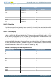
The results are presented in 2’s complement form and the format for differential and single ended mode
is given in Table 28.1 (p. 687) and Table 28.2 (p. 688) . If differential mode is selected, the results
are sign extended up to 32-bit (shown in Table 28.4 (p. 689) ).
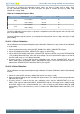
Table 28.1. ADC Single Ended Conversion
Results
Input/Reference
Binary Hex value
1 111111111111 FFF
0.5 011111111111 7FF
1/4096 000000000001 001
0 000000000000 000