
User manual


...the world's most energy friendly microcontrollers
2012-04-24 - Giant Gecko Family - d0053_Rev0.96 668
www.energymicro.com
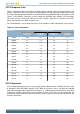
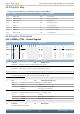
Bit Name Reset Access Description
29:28 CSRESSEL 0x0 RW Capacitive Sense Mode Internal Resistor Select
These bits select the resistance value for the internal capacitive sense resistor. Resulting actual resistor values are given in the
device datasheets.
Value Mode Description
0 RES0 Internal capacitive sense resistor value 0
1 RES1 Internal capacitive sense resistor value 1
2 RES2 Internal capacitive sense resistor value 2
3 RES3 Internal capacitive sense resistor value 3
27:25 Reserved
To ensure compatibility with future devices, always write bits to 0. More information in Section 2.1 (p. 3)
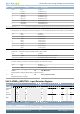
24 CSRESEN 0 RW Capacitive Sense Mode Internal Resistor Enable
Enable/disable the internal capacitive sense resistor.
23:17 Reserved
To ensure compatibility with future devices, always write bits to 0. More information in Section 2.1 (p. 3)
16 LPREF 1 RW Low Power Reference Mode
Enable low power mode for VDD and bandgap references.
Value Description
0 Low power mode disabled
1 Low power mode enabled
15:14 Reserved
To ensure compatibility with future devices, always write bits to 0. More information in Section 2.1 (p. 3)
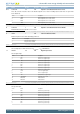
13:8 VDDLEVEL 0x00 RW VDD Reference Level
Select scaling factor for VDD reference level.V
DD_SCALED
= V
DD
×VDDLEVEL/63
7:4 NEGSEL 0x8 RW Negative Input Select
Select negative input.
Value Mode Description
0 CH0 Channel 0 as negative input
1 CH1 Channel 1 as negative input
2 CH2 Channel 2 as negative input
3 CH3 Channel 3 as negative input
4 CH4 Channel 4 as negative input
5 CH5 Channel 5 as negative input
6 CH6 Channel 6 as negative input
7 CH7 Channel 7 as negative input
8 1V25 1.25 V as negative input
9 2V5 2.5 V as negative input
10 VDD Scaled VDD as negative input
11 CAPSENSE Capacitive sense mode
12 DAC0CH0 DAC0 channel 0
13 DAC0CH1 DAC0 channel 1
3 Reserved
To ensure compatibility with future devices, always write bits to 0. More information in Section 2.1 (p. 3)
2:0 POSSEL 0x0 RW Positive Input Select
Select positive input.
Value Mode Description
0 CH0 Channel 0 as positive input
1 CH1 Channel 1 as positive input
2 CH2 Channel 2 as positive input
3 CH3 Channel 3 as positive input
4 CH4 Channel 4 as positive input
5 CH5 Channel 5 as positive input
6 CH6 Channel 6 as positive input
7 CH7 Channel 7 as positive input