
User manual


...the world's most energy friendly microcontrollers
2012-04-24 - Giant Gecko Family - d0053_Rev0.96 663
www.energymicro.com
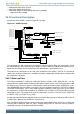
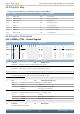
26.3.2 Response Time
There is a delay from when the actual input voltage changes polarity, to when the output toggles. This
period is called the response time and can be altered by increasing or decreasing the bias current to
the comparator through the BIASPROG, FULLBIASPROG and HALFBIAS fields in the ACMPn_CTRL
register, as described in Table 26.1 (p. 663) .Setting the HALFBIAS bit in ACMPn_CTRL effectively
halves the current as observed in Table 26.1 (p. 663) . Setting a lower bias current will result in lower
power consumption, but a longer response time.
If the FULLBIAS bit is set, the highest hysteresis level should be used to avoid glitches on the output.
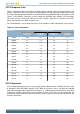
Table 26.1. Bias Configuration
Bias Current (µA)BIASPROG
FULLBIAS=0,
HALFBIAS=1
FULLBIAS=0,
HALFBIAS=0
FULLBIAS=1,
HALFBIAS=1
FULLBIAS=1,
HALFBIAS=0
0b0000 0.05 0.1 3.3 6.5
0b0001 0.1 0.2 6.5 13
0b0010 0.2 0.4 13 26
0b0011 0.3 0.6 20 39
0b0100 0.4 0.8 26 52
0b0101 0.5 1.0 33 65
0b0110 0.6 1.2 39 78
0b0111 0.7 1.4 46 91
0b1000 1.0 2.0 65 130
0b1001 1.1 2.2 72 143
0b1010 1.2 2.4 78 156
0b1011 1.3 2.6 85 169
0b1100 1.4 2.8 91 182
0b1101 1.5 3.0 98 195
0b1110 1.6 3.2 104 208
0b1111 1.7 3.4 111 221
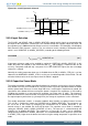
26.3.3 Hysteresis
In the analog comparator, hysteresis can be configured to 8 different levels, including off which is level
0, through the HYSTSEL field in ACMPn_CTRL. When the hysteresis level is set above 0, the digital
output will not toggle until the positive input voltage is at a voltage equal to the hysteresis level above
or below the negative input voltage (see Figure 26.2 (p. 664) ). This feature can be used to filter out
uninteresting input fluctuations around zero and only show changes that are big enough to breach the
hysteresis threshold.