
User manual


...the world's most energy friendly microcontrollers
2012-04-24 - Giant Gecko Family - d0053_Rev0.96 662
www.energymicro.com
• Configurable output when inactive
• Comparator output direct on PRS
• Comparator output on GPIO through alternate functionality
• Output inversion available
26.3 Functional Description
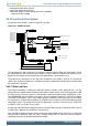
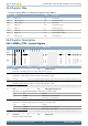
An overview of the ACMP is shown in Figure 26.1 (p. 662) .
Figure 26.1. ACMP Overview
Scaler
1.25 V
2.5 V
ACMPn_CH7
ACMPn_CH0
ACMPn_CH6
ACMPn_CH5
ACMPn_CH4
ACMPn_CH3
ACMPn_CH2
ACMPn_CH1
Output to PRS
Output to GPIO
VDDLEVELNEGSEL
POSSEL
BIASPROG
HYSTSEL
EN
ACMPACT
ACMPOUT
INACTVAL
Warm -up
counter
GPIOINV
000
-
111
0000
-
1101
V
DD
1
0
Read only registers
Read/Write registers
LPREF
Edge interrupt
Warm up interrupt
HALFBIAS
FULLBIAS
V
DD_SCALED
DAC0_CH0
DAC0_CH1
The comparator has two analog inputs, one positive and one negative. When the comparator is active,
the output indicates which of the two input voltages is higher. When the voltage on the positive input is
higher than the voltage on the negative input, the digital output is high and vice versa.
The output of the comparator can be read in the ACMPOUT bit in ACMPn_STATUS. It is possible to
switch inputs while the comparator is enabled, but all other configuration should only be changed while
the comparator is disabled.
26.3.1 Warm-up Time
The analog comparator is enabled by setting the EN bit in ACMPn_CTRL. When this bit is set, the
comparator must stabilize before becoming active and the outputs can be used. This time period is called
the warm-up time. The warm-up time is a configurable number of peripheral clock (HFPERCLK) cycles,
set in WARMTIME, which should be set to at least 10 µs but lengthens to up to 1ms if LPREF is enabled.
The ACMP should always start in active mode and then enable the LPREF after warm-up time. When
the comparator is enabled and warmed up, the ACMPACT bit in ACMPn_STATUS will indicate that the
comparator is active. The output value when the comparator is inactive is set to the value in INACTVAL
in ACMPn_CTRL (see Figure 26.1 (p. 662) ).
An edge interrupt will be generated after the warm-up time if edge interrupt is enabled and the value set
in INACTVAL is different from ACMPOUT after warm-up.
One should wait until the warm-up period is over before entering EM2 or EM3, otherwise no comparator
interrupts will be detected. EM1 can still be entered during warm-up. After the warm-up period is
completed, interrupts will be detected in EM2 and EM3.