
User manual

...the world's most energy friendly microcontrollers
2012-04-24 - Giant Gecko Family - d0053_Rev0.96 659
www.energymicro.com
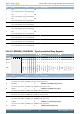
Bit Name Reset Access Description
Value Mode Description
0 LFACLK LFACLK will be used for timing
1 AUXHFRCO AUXHFRCO will be used for timing
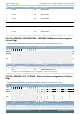
16:15 EXMODE 0xX RW Set GPIO mode
GPIO mode for the excitation phase of the scan sequence. Note that DACOUT is only available on channels 0, 1, 2, 3, 12, 13, 14,
and 15.
Value Mode Description
0 DISABLE Disabled
1 HIGH Push Pull, GPIO is driven high
2 LOW Push Pull, GPIO is driven low
3 DACOUT DAC output
14:13 SETIF 0xX RW Enable interrupt generation
Select interrupt generation mode for CHx interrupt flag.
Value Mode Description
0 NONE No interrupt is generated
1 LEVEL Set interrupt flag if the sensor triggers.
2 POSEDGE Set interrupt flag on positive edge on the sensor state
3 NEGEDGE Set interrupt flag on negative edge on the sensor state
12 SAMPLE X RW Select sample mode
Select if ACMP output or counter output should be used in comparison
Value Mode Description
0 COUNTER Counter output will be used in comparison
1 ACMP ACMP output will be used in comparison
11:0 ACMPTHRES 0xXXX RW Set ACMP threshold
Select ACMP threshold.
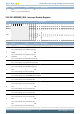
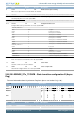
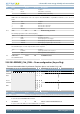
25.5.29 LESENSE_CHx_EVAL - Scan configuration (Async Reg)
For more information about Asynchronous Registers please see Section 5.3 (p. 20) .
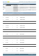
Offset Bit Position
0x2C8
31
30
29
28
27
26
25
24
23
22
21
20
19
18
17
16
15
14
13
12
11
10
9
8
7
6
5
4
3
2
1
0
Reset
X
X
X
X
0xXXXX
Access
RW
RW
RW
RW
RW
Name
SCANRESINV
STRSAMPLE
DECODE
COMP
COMPTHRES
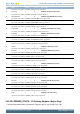
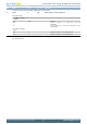
Bit Name Reset Access Description
31:20 Reserved
To ensure compatibility with future devices, always write bits to 0. More information in Section 2.1 (p. 3)
19 SCANRESINV X RW Enable inversion of result
If set, the bit stored in SCANRES will be inverted.
18 STRSAMPLE X RW Select if counter result should be stored
If set, the counter value will be stored and available in the result buffer
17 DECODE X RW Send result to decoder