
User manual

...the world's most energy friendly microcontrollers
2012-04-24 - Giant Gecko Family - d0053_Rev0.96 64
www.energymicro.com
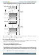
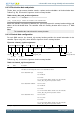
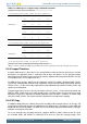
Figure 8.7. Detailed memory map for the 12 channels, including the alternate data structure
0x000
Source End Pointer
Destination End Pointer
Control
Unused
Source End Pointer
Destination End Pointer
Control
Unused
Source End Pointer
Destination End Pointer
Control
Unused
0x004
0x008
0x010
0x014
0x018
0x0B0
0x0B4
0x0B8
Primary for
channel 0
Primary for
channel 1
Primary for
channel 11
Source End Pointer
Destination End Pointer
Control
Unused
0x100
0x104
0x108
Alternate for
channel 0
Alternate for
channel 1
Alternate for
channel 11
Source End Pointer
Destination End Pointer
Control
Unused
0x110
0x114
0x118
Source End Pointer
Destination End Pointer
Control
Unused
0x1B0
0x1B4
0x1B8
0x00C
0x01C
0x0BC
0x10C
0x11C
0x1BC
Primary
data
structure
Alternate
data
structure
The controller uses the system memory to enable it to access two pointers and the control information
that it requires for each channel. The following subsections will describe these 32-bit memory locations
and how the controller calculates the DMA transfer address.
8.4.3.1 Source data end pointer
The src_data_end_ptr memory location contains a pointer to the end address of the source data.
Figure 8.7 (p. 64) lists the bit assignments for this memory location.
Table 8.7. src_data_end_ptr bit assignments
Bit Name Description
[31:0] src_data_end_ptr Pointer to the end address of the source data
Before the controller can perform a DMA transfer, you must program this memory location with the end
address of the source data. The controller reads this memory location when it starts a 2
R
DMA transfer.
Note
The controller does not write to this memory location.