
User manual

...the world's most energy friendly microcontrollers
2012-04-24 - Giant Gecko Family - d0053_Rev0.96 63
www.energymicro.com
• have a base address that is an integer multiple of the total size of the channel control data structure.
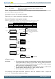
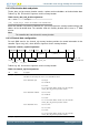
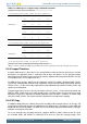
Figure 8.6 (p. 63) shows the memory that the controller requires for the channel control data structure,
when all 12 channels and the optional alternate data structure are in use.
Figure 8.6. Memory map for 12 channels, including the alternate data structure
Primary_Ch_0
Primary_Ch_1
Primary_Ch_2
Primary_Ch_3
Primary_Ch_4
Primary_Ch_5
Primary_Ch_6
Primary_Ch_7
0x000
0x010
0x050
0x080
0x070
0x060
0x040
0x030
0x020
Alternate_Ch_0
Alternate_Ch_1
Alternate_Ch_2
Alternate_Ch_3
Alternate_Ch_4
Alternate_Ch_5
Alternate_Ch_6
Alternate_Ch_7
0x100
0x110
0x150
0x180
0x170
0x160
0x140
0x130
0x120
Destination End Pointer
Source End Pointer
Control
User
0x000
0x004
0x008
0x00C
Alternate data structure
Prim ary data structure
Primary_Ch_8
Primary_Ch_9
Primary_Ch_10
Primary_Ch_11
0x090
0x0C0
0x0B0
0x0A0
Alternate_Ch_8
Alternate_Ch_9
Alternate_Ch_10
Alternate_Ch_11
0x190
0x1C0
0x1B0
0x1A0
This structure in Figure 8.6 (p. 63) uses 448 bytes of system memory. The controller uses the lower
8 address bits to enable it to access all of the elements in the structure and therefore the base address
must be at 0xXXXXXX00.
You can configure the base address for the primary data structure by writing the appropriate value in
the DMA_CTRLBASE register.
You do not need to set aside the full 448 bytes if not all 12 channels are used or not all alternate
descriptors are used. If e.g. only 4 channels are used and they only need the primary descriptors, then
only 64 bytes need be set aside.
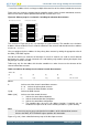
Table 8.6 (p. 63) lists the address bits that the controller uses when it accesses the elements of the
channel control data structure.
Table 8.6. Address bit settings for the channel control data structure
Address bits
[8] [7] [6] [5] [4] [3:0]
A C[3] C[2] C[1] C[0] 0x0, 0x4, or 0x8
Where:
A Selects one of the channel control data structures:
A = 0 Selects the primary data structure.
A = 1 Selects the alternate data structure.
C[3:0] Selects the DMA channel.
Address[3:0] Selects one of the control elements:
0x0 Selects the source data end pointer.
0x4 Selects the destination data end pointer.
0x8 Selects the control data configuration.
0xC The controller does not access this address location. If required, you can
enable the host processor to use this memory location as system memory.
Note
It is not necessary for you to calculate the base address of the alternate data structure
because the DMA_ALTCTRLBASE register provides this information.
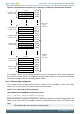
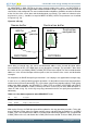
Figure 8.7 (p. 64) shows a detailed memory map of the descriptor structure.