
User manual


...the world's most energy friendly microcontrollers
2012-04-24 - Giant Gecko Family - d0053_Rev0.96 619
www.energymicro.com
is clocked by LFACLK
LESENSE
. This counter has its own prescaler. This prescaling factor is configured in
PCPRESC in TIMCTRL. A new scan sequence is started each time the counter reaches the top value,
PCTOP. The scan frequency is calculated using Equation 25.1 (p. 619) . If SCANMODE is set to
ONESHOT, a single scan will be made when START in CMD is set. To start a new scan on a PRS
event, set SCANMODE to PRS and configure PRS channel in PRSSEL. The PRS start signal needs to
be active for at least one LFACLK
LESENSE
cycle to make sure LESENSE is able to register it.
Scan frequency
F
scan
= LFACLK
LESENSE
/((1 + PCTOP)*2
PCPRESC
) (25.1)
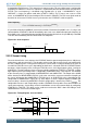
It is possible to interleave additional sensor measurements in between the periodic scans. Issuing a start
command when LESENSE is idle will immediately start a new scan, without disrupting the frequency of
the periodic scans. If the period counter overflows during the interleaved scan, the periodically scheduled
scan will start immediately after the interleaved scan completes.
Figure 25.2. Scan sequence
CH3 CH5 CH9 CH3 CH5 CH9
START START
Scan period
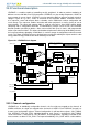
25.3.3 Sensor timing
For each channel in the scan sequence, the LESENSE interface goes through three phases: Idle phase,
excite phase, and measure phase. The durations of the excite and measure phases are configured in
the CHx_TIMING registers. Timing of the excite phase can be either a number of AUXHFRCO cycles or
a number of LFACLK
LESENSE
cycles, depending on which one is selected in EXCLK. LESENSE includes
two timers: A low frequency timer, running on LFACLK
LESENSE
, and a high frequency timer, running on
AUXHFRCO. The low frequency timer can be prescaled by configuring LFPRESC in TIMCTRL, and the
high frequency timer prescaling factor is configured in AUXPRESC in the same register. The duration
of the measure phase is programmed via MEASUREDLY and SAMPLEDLY. The output of the ACMP
will be inactive for MEASUREDLY EXCLK cycles after start of the sensor measurement. Sampling of
the sensor will happen after SAMPLEDLY LFACLK
LESENSE
, or AUXHFRCO cycles, depending on the
configuration of SAMPLECLK. Figure 25.3 (p. 619) depicts a sensor sequence where excitation and
measure delay is timed using AUXHFRCO and the sample delay is timed using LFACLK
LESENSE
. The
configurable measure- and sample delays enables LESENSE to easily define exact time windows for
sensor measurements. A start delay can be inserted before sensor measurement begin by configuring
STARTDLY in TIMCTRL. This delay can be used to ensure that the DAC is done and voltages have
stabilized before sensor measurement begins.
Figure 25.3. Timing diagram, short excitation
EXCITE
SAMPLE
LFACLK
LESENSE
Idle phase Excite phase Idle phase
Sam ple delay
Measure phase
START
AUXHFRCO
INIT
Start delay
Measure delay
DAC refresh start