
User manual


...the world's most energy friendly microcontrollers
2012-04-24 - Giant Gecko Family - d0053_Rev0.96 617
www.energymicro.com
25.3 Functional description
LESENSE is a module capable of controlling on-chip peripherals in order to perform monitoring of
different sensors with little or no CPU intervention. LESENSE uses the analog comparators, ACMP, for
measurement of sensor signals. LESENSE can also control the DAC to generate accurate reference
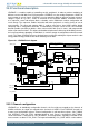
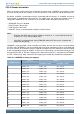
voltages. Figure 25.1 (p. 617) shows an overview of the LESENSE module. LESENSE consists
of a sequencer, count and compare block, a decoder, and a RAM block used for configuration and
result storage. The sequencer handles interaction with other peripherals as well as timing of sensor
measurements. The count and compare block is used to count pulses from ACMP outputs before
comparing with a configurable threshold. To autonomously analyze sensor results, the LESENSE
decoder provides possibility to define a finite state machine with up to 16 states, and programmable
actions upon state transitions. This allows the decoder to implement a wide range of decoding schemes,
for instance quadrature decoding. A RAM block is used for storage of configuration and measurement
results. This allows LESENSE to have a relatively large result buffer enabling the chip to remain in a low
energy mode for long periods of time while collecting sensor data.
Figure 25.1. LESENSE block diagram
LESENSE
Counter
Com pare
Decoder
PRS input
DAC0
AUXHFRCO
ACMP1
ACMP1_CHn
LES_ALTEXn
Register bitfields
overridden by LESENSE
Scaler
1.25 V
2.5 V
V
DD
V
SS
ACMP0
ACMP0_CHn
PRS
CH0 CH1
DAC0_CH0
DAC0_CH1
DAC0_CH0
DAC0_CH1
DAC0_CH0
DAC0_CH1
Scaler
1.25 V
2.5 V
V
DD
V
SS
DAC0_CH0
DAC0_CH1
ACMP0INV
ACMP1INV
VDDLEVEL
POSSEL
POSSEL
VDDLEVEL
RAMSequencer
ACMP sample reg
CONVMODE*
OUTMODE*
CHxCTRL_EN
CHxDATA
DAC
interface
* LESENSE controls CONVMODE and
OUTMODE individually for t he DAC
channels
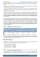
25.3.1 Channel configuration
LESENSE has 16 individually configurable channels, the first eight are mapped to the channels of
ACMP0, while the last eight are mapped to the channels of ACMP1. Each LESENSE channel has
its own set of configuration registers. Channel configuration is split into three registers; CHx_TIMING,
CHx_INTERACT, and CHx_EVAL. Individual timing for each sensor is configured in CHx_TIMING,
sensor interaction is configured in CHx_INTERACT, and configurations regarding evaluation of the
measurements are done in CHx_EVAL. For improved readability, CHx_CONF will be used to address