
User manual

...the world's most energy friendly microcontrollers
2012-04-24 - Giant Gecko Family - d0053_Rev0.96 604
www.energymicro.com
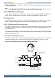
The direction of the quadrature code and control of the counter is generated by the simple binary function
outlined by Table 24.1 (p. 604) . Note that this function also filters some invalid inputs that may occur
when the shaft changes direction or temporarily toggles direction.
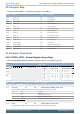
Table 24.1. PCNT QUAD Mode Counter Control Function
Inputs Control/Status
S1IN posedge S1IN negedge Count Enable CNTDIR status bit
0 0 0 0
0 1 1 0
1 0 1 1
1 1 0 0
Note
PCNTn_S1IN is sampled on both edges of PCNTn_S0IN.
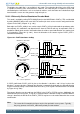
24.3.2 Hysteresis
By default the pulse counter wraps to 0 when passing the configured top value, and wraps to the top
value when counting down from 0. On these events, a system will likely want to wake up to store and
track the overflow count. This is fine if the pulse counter is tracking a monotonic value or a value that
does not change directions frequently. If you have the latter however, and the counter changes directions
around the overflow/underflow point, the system will have to wake up a lot to keep track of the rotations,
causing high current consumptions
To solve this, the pulse counter has a way of introducing hysteresis to the counter. When HYST in
PCNTn_CTRL is set, the pulse counter will always wrap to TOP/2 on underflows and overflows. This
takes the counter away from the area where it might overflow or underflow, removing the problem.
Given a starting value of 0 for the counter, the absolute count value when hysteresis is enabled can
be calculated with the equations Equation 24.1 (p. 604) or Equation 24.2 (p. 604) , depending on
whether the TOP value is even or odd.
Absolute position with hysteresis and even TOP value
CNT
abs
= CNT - UF
CNT
x (TOP/2+1) + OF
CNT
x (TOP/2+1) (24.1)
Absolute position with hysteresis and odd TOP value
CNT
abs
= CNT - UF
CNT
x (TOP/2+1) + OF
CNT
x (TOP/2+2) (24.2)
24.3.3 Auxillary counter
To be able to keep explicit track of counting in one direction in addition to the regular counter which
counts both up and down, the auxillary counter can be used. The pulse counter can for instance be
configured to keep track of the absolute rotation of the wheel, and at the same time the auxillary counter
kan keep track of how much the wheel has reversed.
The auxillary counter is enabled by configuring AUXCNTEV in PCNTn_CTRL. It will always count up,
but it can be configured whether it should count up on up-events, down-events or both, keeping track
of rotation either way or general movement. The value of the auxillary counter can be read from the
PCNTn_AUXCNT register.
Overflows on the auxillary counter happen when the auxillary counter passes the top value of the pulse
counter, configured in PCNTn_TOP. In that event, the AUXOF interrupt flag is set, and the auxillary
counter wraps to 0.