
User manual

...the world's most energy friendly microcontrollers
2012-04-24 - Giant Gecko Family - d0053_Rev0.96 602
www.energymicro.com
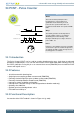
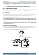
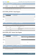
Figure 24.1. PCNT Overview
Peripheral bus
CNT
PCNTn_S0IN
Pulse Width
Filter
Inverter
PCNTn_S1IN
Inverter
Count
Enable
1
LFACLK
Clock
switch
CMU (conseptual)
TOPB
Quadrature
decoder
Edge
detect or
OVR_SINGLE
EXTCLK_SINGLE
EXTCLK_QUAD
TOP
S0PRS Input
Analog de-glitch filter
S1PRS Input
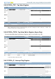
24.3.1 Pulse Counter Modes
The pulse counter can operate in single input oversampling mode (OVSSINGLE), externally clocked
single input counter mode (EXTCLKSINGLE) and externally clocked quadrature decoder mode
(EXTCLKQUAD). The following sections describe operation of each of the three modes and how they
are enabled. Input timing constraints are described in Section 24.3.5 (p. 605) and Section 24.3.6 (p.
605) .
24.3.1.1 Single Input Oversampling Mode
This mode is enabled by writing OVSSINGLE (0x1) to the MODE field in the PCNTn_CTRL register and
disabled by writing DISABLE (0x0) to the same field. LFACLK is configured from the registers in the
Clock Management Unit (CMU), Chapter 11 (p. 126) .
The optional pulse width filter is enabled by setting the FILT bit in the PCNTn_CTRL register. Additionally,
the PCNTn_S0IN input may be inverted, so that falling edges are counted, by setting the EDGE bit in
the PCNTn_CTRL register.
If S1CDIR is cleared, PCNTn_S0IN is the only observed input in this mode. The PCNTn_S0IN input
is sampled by the LFACLK and the number of detected positive or negative edges on PCNTn_S0IN
appears in PCNTn_CNT. The counter may be configured to count down by setting the CNTDIR bit in
PCNTn_CTRL. Default is to count up.
The counting direction can also be controlled externally in this mode by setting S1CDIR in PCNTn_CTRL.
This will make the input value on PCNTn_S1IN decide the direction counted on a PCNTn_S0IN edge.
If PCNTn_S1IN is high, the count is done according to CNTDIR in PCNTn_CTRL. If low, the count
direction is opposite.
24.3.1.2 Externally Clocked Single Input Counter Mode
This mode is enabled by writing EXTCLKSINGLE (0x2) to the MODE field in the PCNTn_CTRL register
and disabled by writing DISABLE (0x0) to the same field. The external pin clock source must be
configured from the registers in the CMU (Chapter 11 (p. 126) ).
Positive edges on PCNTn_S0IN are used to clock the counter. Similar to the oversampled mode,
PCNTn_S1IN is used to determine the count direction if S1CDIR in PCNTn_CTRL is set. If not, CNTDIR
in PCNTn_CTRL solely defines count direction. As the LFACLK is not used in this mode, the PCNT
module can operate in EM3.