
User manual


...the world's most energy friendly microcontrollers
2012-04-24 - Giant Gecko Family - d0053_Rev0.96 557
www.energymicro.com
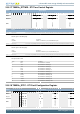
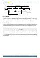
Figure 21.1. RTC Overview
Counter (CNT)
Peripheral bus
=
Compare match 1
Compare match 0
RTC Control and
Status
=
LFACLK
RTC
Compare 0
(COMP0)
Compare 1
(COMP1)
Clear
21.3.1 Counter
The RTC is enabled by setting the EN bit in the RTC_CTRL register. It counts up as long as it is
enabled, and will on an overflow simply wrap around and continue counting. The RTC is cleared when
it is disabled. The timer value is both readable and writable and the RTC always starts counting from 0
when enabled. The value of the counter can be read or modified using the RTC_CNT register.
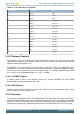
21.3.1.1 Clock Source
The RTC clock source and its prescaler value are defined in the Register Description section of the Clock
Management Unit (CMU). The clock used by the RTC has a frequency given by Equation 21.1 (p. 557) .
RTC Frequency Equation
f
RTC
= f
LFACLK
/2
RTC_PRESC
(21.1)
where f
LFACLK
is the LFACLK frequency (32.768 kHz) and RTC_PRESC is a 4 bit value. Table 21.1 (p.
558) shows the time of overflow and resolution of the RTC at the available prescaler values.
To use this module, the LE interface clock must be enabled in CMU_HFCORECLKEN0 in addition to
the module clock