
User manual


...the world's most energy friendly microcontrollers
2012-04-24 - Giant Gecko Family - d0053_Rev0.96 548
www.energymicro.com
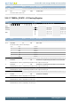
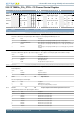
Bit Name Reset Access Description
Value Mode Description
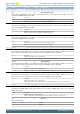
8 PRSCH8 PRS Channel 8 selected as input
9 PRSCH9 PRS Channel 9 selected as input
10 PRSCH10 PRS Channel 10 selected as input
11 PRSCH11 PRS Channel 11 selected as input
15:14 Reserved
To ensure compatibility with future devices, always write bits to 0. More information in Section 2.1 (p. 3)
13:12 CUFOA 0x0 RW Counter Underflow Output Action
Select output action on counter underflow.
Value Mode Description
0 NONE No action on counter underflow
1 TOGGLE Toggle output on counter underflow
2 CLEAR Clear output on counter underflow
3 SET Set output on counter underflow
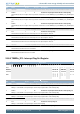
11:10 COFOA 0x0 RW Counter Overflow Output Action
Select output action on counter overflow.
Value Mode Description
0 NONE No action on counter overflow
1 TOGGLE Toggle output on counter overflow
2 CLEAR Clear output on counter overflow
3 SET Set output on counter overflow
9:8 CMOA 0x0 RW Compare Match Output Action
Select output action on compare match.
Value Mode Description
0 NONE No action on compare match
1 TOGGLE Toggle output on compare match
2 CLEAR Clear output on compare match
3 SET Set output on compare match
7:5 Reserved
To ensure compatibility with future devices, always write bits to 0. More information in Section 2.1 (p. 3)
4 COIST 0 RW Compare Output Initial State
This bit is only used in Output Compare and PWM mode. When this bit is set in compare mode,the output is set high when the counter
is disabled. When counting resumes, this value will represent the initial value for the output. If the bit is cleared, the output will be
cleared when the counter is disabled. In PWM mode, the output will always be low when disabled, regardless of this bit. However,
this bit will represent the initial value of the output, once it is enabled.
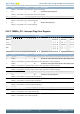
3 Reserved
To ensure compatibility with future devices, always write bits to 0. More information in Section 2.1 (p. 3)
2 OUTINV 0 RW Output Invert
Setting this bit inverts the output from the CC channel (Output compare,PWM).
1:0 MODE 0x0 RW CC Channel Mode
These bits select the mode for Compare/Capture channel.
Value Mode Description
0 OFF Compare/Capture channel turned off
1 INPUTCAPTURE Input capture
2 OUTPUTCOMPARE Output compare
3 PWM Pulse-Width Modulation