
User manual


...the world's most energy friendly microcontrollers
2012-04-24 - Giant Gecko Family - d0053_Rev0.96 536
www.energymicro.com
Each of the events has its own interrupt flag. Also, there is one interrupt flag for each Compare/Capture
channel which is set on buffer overflow in capture mode. Buffer overflow happens when a new capture
pushes an old unread capture out of the TIMERn_CCx_CCV/TIMERn_CCx_CCVB register pair.
If the interrupt flags are set and the corresponding interrupt enable bits in TIMERn_IEN) are set high,
the Timer will send out an interrupt request. Each of the events will also lead to a one HFPERCLK
TIMERn
cycle high pulse on individual PRS outputs.
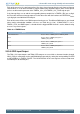
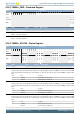
Each of the events will also set a DMA request when they occur. The different DMA requests are cleared
when certain acknowledge conditions are met, see Table 20.3 (p. 536) . If DMACLRACT is set in
TIMERn_CTRL, the DMA request is cleared when the triggered DMA channel is active, without having
to access any timer registers.
Table 20.3. TIMER Events
Event Acknowledge
Underflow/Overflow Read or write to TIMERn_CNT or TIMERn_TOPB
CC 0 Read or write to TIMERn_CC0_CCV or
TIMERn_CC0_CCVB
CC 1 Read or write to TIMERn_CC1_CCV or
TIMERn_CC1_CCVB
CC 2 Read or write to TIMERn_CC2_CCV or
TIMERn_CC2_CCVB
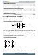
20.3.6 GPIO Input/Output
The TIMn_CCx inputs/outputs and TIM0_CDTIx outputs are accessible as alternate functions through
GPIO. Each pin connection can be enabled/disabled separately by setting the corresponding CCxPEN
or CDTIxPEN bits in TIMERn_ROUTE. The LOCATION bits in the same register can be used to move
all enabled pins to alternate pins.