
User manual

...the world's most energy friendly microcontrollers
2012-04-24 - Giant Gecko Family - d0053_Rev0.96 530
www.energymicro.com
R
PWM
up
= log(TOP+1)/log(2) (20.3)
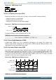
The PWM frequency is given by Equation 20.4 (p. 530) :
TIMER Up-count PWM Frequency Equation
f
PWM
up/down
= f
HFPERCLK
/ ( 2^PRESC x (TOP + 1) (20.4)
The high duty cycle is given by Equation 20.5 (p. 530)
TIMER Up-count Duty Cycle Equation
DS
up
= CCVx/TOP (20.5)
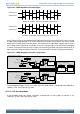
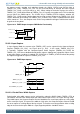
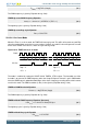
20.3.2.6.1 2x Count Mode
When the Timer is set in 2x mode, the TIMER will count up by two. This will in effect make any odd Top
value be rounded down to the closest even number. Similarly, any odd CC value will generate a match
on the closest lower even value as shown in Figure 20.19 (p. 530)
Figure 20.19. TIMER CC out in 2x mode
2 4 0 2 40
Clock
CC Out
0
2 4 0 2 40
0
Top = 5
CC = 1
Top = 5
CC = 2
The mode is enabled by setting the X2CNT field in TIMERn_CTRL register. The intended use of the
2x mode is to generate 2x PWM frequency when the Compare/Capture channel is put in PWM mode.
Since the PWM output is updated on both edges of the clock, frequency prescaling will result in incorrect
result in this mode. The PWM resolution (in bits) is then given by Equation 20.6 (p. 530) .
TIMER 2x PWM Resolution Equation
R
PWM
2xmode
= log(TOP/2+1)/log(2) (20.6)
The PWM frequency is given by Equation 20.7 (p. 530) :
TIMER 2x Mode PWM Frequency Equation( Up-count)
f
PWM
2xmode
= 2 x f
HFPERCLK
/ floor(TOP/2)+1 (20.7)
The high duty cycle is given by Equation 20.8 (p. 530)
TIMER 2x Mode Duty Cycle Equation
DS
2xmode
= CCVx/TOP (20.8)