
User manual

...the world's most energy friendly microcontrollers
2012-04-24 - Giant Gecko Family - d0053_Rev0.96 529
www.energymicro.com
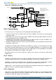
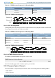
Figure 20.16. TIMER Output Logic
TIMn_CCx
COIST
OUTINV
Output
Com pare/
PWM x
0
1
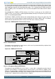
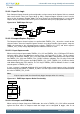
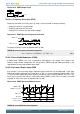
20.3.2.4.1 Frequency Generation (FRG)
Frequency generation (see Figure 20.17 (p. 529) ) can be achieved in compare mode by:
• Setting the counter in up-count mode
• Enabling buffering of the TOP value.
• Setting the CC channels overflow action to toggle
Figure 20.17. TIMER Up-count Frequency Generation
0
TIMERn_TOP
TIMERn_CCx_CCV
The output frequency is given by Equation 20.2 (p. 529)
TIMER Up-count Frequency Generation Equation
f
FRG
= f
HFPERCLK
/ ( 2^(PRESC + 1) x (TOP + 1) ) (20.2)
20.3.2.5 Pulse-Width Modulation (PWM)
In PWM mode, TIMERn_CCx_CCV is buffered to avoid glitches in the output. The settings in the
Compare Output Action configuration bits are ignored in PWM mode and PWM generation is only
supported for up-count and up/down-count mode.
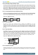
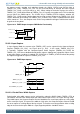
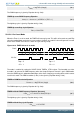
20.3.2.6 Up-count (Single-slope) PWM
If the counter is set to up-count and the Compare/Capture channel is put in PWM mode, single slope
PWM output will be generated (see Figure 20.18 (p. 529) ). In up-count mode the PWM period is TOP
+1 cycles and the PWM output will be high for a number of cycles equal to TIMERn_CCx_CCV. This
means that a constant high output is achieved by setting TIMER_CCx to TOP+1 or higher. The PWM
resolution (in bits) is then given by Equation 20.3 (p. 529) .
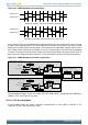
Figure 20.18. TIMER Up-count PWM Generation
0
TIMERn_TOP
TIMERn_CCx_CCV
TIMn_CCx
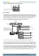
Overflow
Compare match
Buffer update
TIMER Up-count PWM Resolution Equation