
User manual

...the world's most energy friendly microcontrollers
2012-04-24 - Giant Gecko Family - d0053_Rev0.96 527
www.energymicro.com
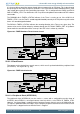
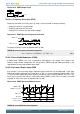
on compare match, overflow and underflow through the CMOA, COFOA and CUFOA fields in
TIMERn_CCx_CTRL. TIMERn_CCx_CCV can be accessed directly or through the buffer register
TIMERn_CCx_CCVB, see Figure 20.12 (p. 527) . When writing to the buffer register, the value in
TIMERn_CCx_CCVB will be written to TIMERn_CCx_CCV on the next update event. This functionality
ensures glitch free PWM outputs. The CCVBV flag in TIMERn_STATUS indicates whether the
TIMERn_CCx_CCVB register contains data that have not yet been written to the TIMERn_CCx_CCV
register. Note that when writing 0 to TIMERn_CCx_CCVB the CCV value is updated when the timer
counts from 0 to 1. Thus, the compare match for the next period will not happen until the timer reaches
0 again on the way down.
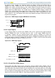
Figure 20.12. TIMER Output Compare/PWM Buffer Functionality
CCV
APB Write (CCB)
CCVB
Load APB
Load APB
CCVBV
Set
Clear
APB Write (CC)
Update event
Load CCB
APB Data
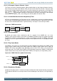
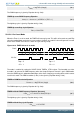
20.3.2.3 Input Capture
In Input Capture Mode, the counter value (TIMERn_CNT) can be captured in the Compare/Capture
Register (TIMERn_CCx_CCV), see Figure 20.13 (p. 527) . In this mode, TIMERn_CCx_CCV
is read-only. Together with the Compare/Capture Buffer Register (TIMERn_CCx_CCVB) the
TIMERn_CCx_CCV form a double-buffered capture registers allowing two subsequent capture events
to take place before a read-out is required. The CCPOL bits in TIMERn_STATUS indicate the polarity
the edge that triggered the capture in TIMERn_CCx_CCV.
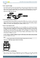
Figure 20.13. TIMER Input Capture
TIMERn_CCx_CCV
m
m
n
y
z
TIMERn_CNT
Input
Read TIMERn_CCx_CCVB
TIMERn_CCx_CCVB
m y
prev. val
prev. val
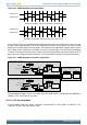
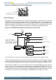
20.3.2.3.1 Period/Pulse-Width Capture
Period and/or pulse-width capture can be achieved by setting the RISEA field in TIMERn_CTRL to
Clear&Start, and select the wanted input from either external pin or PRS, see Figure 20.14 (p. 528) .
For period capture, the Compare/Capture Channel should then be set to input capture on a rising edge
of the same input signal. To capture a the width of a high pulse, the Compare/Capture Channel should
be set to capture on a falling edge of the input signal. To start the measuring period on either a falling
edge or measure the low pulse-width of a signal, opposite polarities should be chosen.