
User manual

...the world's most energy friendly microcontrollers
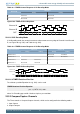
2012-04-24 - Giant Gecko Family - d0053_Rev0.96 524
www.energymicro.com
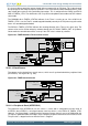
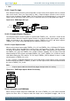
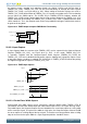
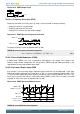
Figure 20.6. TIMER Quadrature Encoded Inputs
Channel A
Channel B
Forward rotation (Channel A leads Channel B)
90°
Channel A
Channel B
Backward rotation (Channel B leads Channel A)
90°
In the Timer these inputs are tapped from the Compare/Capture channel 0 (Channel A) and 1 (Channel
B) inputs before edge detection. The Timer/Counter then increments or decrements the counter, based
on the phase relation between the two inputs. The Quadrature Decoder Mode supports two channels,
but if a third channel (Z-terminal) is available, this can be connected to an external interrupt and trigger
a counter reset from the interrupt service routine. By connecting a periodic signal from another timer as
input capture on Compare/Capture Channel 2, it is also possible to calculate speed and acceleration.
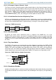
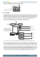
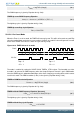
Figure 20.7. TIMER Quadrature Decoder Configuration
Count er
(Controlled by TIMERn_CTRL)
Com pare/Capture channel 1
(Controlled by TIMERn_CC1_CTRL)
Com pare/Capture channel 0
(Controlled by TIMERn_CC0_CTRL)
TIMn_CC0
PRS channels
PRSSEL
INSEL
Filter
FILT
ICEDGE
Quadrat ure
Decoder
TIMn_CC1
PRS channels
PRSSEL
INSEL
Filter
FILT
ICEDGE
Input
Capture 0
Input
Capture 1
Count er
Inc
Dec
QDM MODE
Ch B
Ch A
The Quadrature Decoder can be set in either X2 or X4 mode, which is configured in the QDM bit in
TIMERn_CTRL. See Figure 20.7 (p. 524)
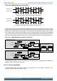
20.3.1.6.1 X2 Decoding Mode
In X2 Decoding mode, the counter increments or decrements on every edge of Channel A, see
Table 20.1 (p. 525) and Figure 20.8 (p. 525) .