
User manual

...the world's most energy friendly microcontrollers
2012-04-24 - Giant Gecko Family - d0053_Rev0.96 521
www.energymicro.com
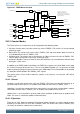
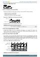
Figure 20.1. TIMER Block Overview
=
=
Com pare and
PWM config
Com pare and
PWM config
Com pare and
PWM config
=
TnCCR0[15:0
]
TnCCR1[15:0
]
Com pare Match x
TIMERn_TOPTIMERn_CNT
TIMERn_CCx
Input Capture
Update
condition
Note: For simplicity, all
TIMERn_CCx registers are
grouped together in the figure,
but they all have individual Input
Capture Registers
=
= 0
CNTCLK
Counter
control
Overflow
Underflow
TIMn_CC0
Input logic
Edge
detect
Quadrature
Decoder
Input logic
Input logic
Edge
detect
Edge
detect
PRS inputs
PRS inputs
PRS inputs
Prescaler
HFPERCLK
TIMERn
TIMn_CC1
TIMn_CC2
TIMn_CC0
TIMn_CC1
TIMn_CC2
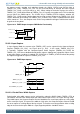
20.3.1 Counter Modes
The Timer consists of a counter that can be configured to the following modes:
1. Up-count: Counter counts up until it reaches the value in TIMERn_TOP, where it is reset to 0 before
counting up again.
2. Down-count: The counter starts at the value in TIMERn_TOP and counts down. When it reaches 0,
it is reloaded with the value in TIMERn_TOP.
3. Up/Down-count: The counter starts at 0 and counts up. When it reaches the value in TIMERn_TOP,
it counts down until it reaches 0 and starts counting up again.
4. Quadrature Decoder: Two input channels where one determines the count direction, while the other
pin triggers a clock event.
In addition, to the TIMER modes listed above, the TIMER also supports a 2x Count Mode. In this mode
the counter increments/decrements by 2. The 2x Count Mode intended use is to generate 2x PWM
frequency when the Compare/Capture channel is put in PWM mode. The 2x Count Mode can be enabled
by setting the X2CNT bitfield in the TIMERn_CTRL register.
The counter value can be read or written by software at any time by accessing the CNT field in
TIMERn_CNT.
20.3.1.1 Events
Overflow is set when the counter value shifts from TIMERn_TOP to the next value when counting up. In
up-count mode the next value is 0. In up/down-count mode, the next value is TIMERn_TOP-1.
Underflow is set when the counter value shifts from 0 to the next value when counting down. In down-
count mode, the next value is TIMERn_TOP. In up/down-count mode the next value is 1.
Update event is set on overflow in up-count mode and on underflow in down-count or up/down count
mode. This event is used to time updates of buffered values.
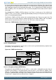
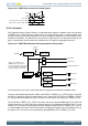
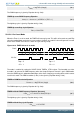
20.3.1.2 Operation
Figure 20.2 (p. 522) shows the hardware Timer/Counter control. Software can start or stop the counter
by writing a 1 to the START or STOP bits in TIMERn_CMD. The counter value (CNT in TIMERn_CNT)
can always be written by software to any 16-bit value.