
User manual


...the world's most energy friendly microcontrollers
2012-04-24 - Giant Gecko Family - d0053_Rev0.96 520
www.energymicro.com
• Period measurement
• Pulse width measurement
• Two capture registers for each capture channel
• Capture on either positive or negative edge
• Capture on both edges
• Optional digital noise filtering on capture inputs
• Output Compare
• Compare output toggle/pulse on compare match
• Immediate update of compare registers
• PWM
• Up-count PWM
• Up/down-count PWM
• Predictable initial PWM output state (configured by SW)
• Buffered compare register to ensure glitch-free update of compare values
• Clock sources
• HFPERCLK
TIMERn
• 10-bit Prescaler
• External pin
• Peripheral Reflex System
• Debug mode
• Configurable to either run or stop when processor is stopped (break)
• Interrupts, PRS output and/or DMA request
• Underflow
• Overflow
• Compare/Capture event
• Dead-Time Insertion Unit (TIMER0 only)
• Complementary PWM outputs with programmable dead-time
• Dead-time is specified independently for rising and falling edge
• 10-bit prescaler
• 6-bit time value
• Outputs have configurable polarity
• Outputs can be set inactive individually by software.
• Configurable action on fault
• Set outputs inactive
• Clear output
• Tristate output
• Individual fault sources
• One or two PRS signals
• Debugger
• Support for automatic restart
• Core lockup
• Configuration lock
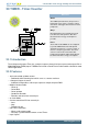
20.3 Functional Description
An overview of the TIMER module is shown in Figure 20.1 (p. 521) . The Timer module consists of
a 16 bit up/down counter with 3 Compare/Capture channels connected to pins TIMn_CC0, TIMn_CC1,
and TIMn_CC2.