
User manual


...the world's most energy friendly microcontrollers
2012-04-24 - Giant Gecko Family - d0053_Rev0.96 48
www.energymicro.com
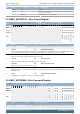
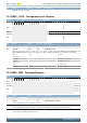
Bit Name Reset Access Description
31:17 Reserved
To ensure compatibility with future devices, always write bits to 0. More information in Section 2.1 (p. 3)
16 PERIOD 0 RW Sets the timebase period
Decides whether TIMEBASE specifies the number of AUX cycles in 1 us or 5 us
Value Mode Description
0 1US TIMEBASE period is 1 us
1 5US TIMEBASE period is 5 us
15:6 Reserved
To ensure compatibility with future devices, always write bits to 0. More information in Section 2.1 (p. 3)
5:0 BASE 0x10 RW Timebase used by MSC to time flash writes and erases
Should be set to the number of AUX clock cycles-1 in 1.1 us if PERIOD is cleared, or the number of AUX clock cycles-1 in 5.5 us if
PERIOD is set. The value should be rounded up to make sure the number of clock cycles generate at least the specified time. The
resetvalue of the timebase matches a 14 MHz AUXHFRCO, which is the default frequency of the AUXHFRCO.
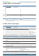
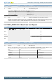
7.5.17 MSC_MASSLOCK - Mass Erase Lock Register
Offset Bit Position
0x054
31
30
29
28
27
26
25
24
23
22
21
20
19
18
17
16
15
14
13
12
11
10
9
8
7
6
5
4
3
2
1
0
Reset
0x0001
Access
RW
Name
LOCKKEY
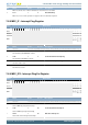
Bit Name Reset Access Description
31:16 Reserved
To ensure compatibility with future devices, always write bits to 0. More information in Section 2.1 (p. 3)
15:0 LOCKKEY 0x0001 RW Mass Erase Lock
Write any other value than the unlock code to lock access the the ERASEMAIN0 and ERASEMAIN1 commands. Write the unlock
code 631A to enable access. When reading the register, bit 0 is set when the lock is enabled. Locked by default
Mode Value Description
Read Operation
UNLOCKED 0 Mass erase unlocked
LOCKED 1 Mass erase locked
Write Operation
LOCK 0 Lock mass erase
UNLOCK 0x631A Unlock mass erase