
User manual


...the world's most energy friendly microcontrollers
2012-04-24 - Giant Gecko Family - d0053_Rev0.96 475
www.energymicro.com
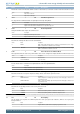
Bit Name Reset Access Description
Value Mode Description
3 TWO The transmitter generates two stop bits. The receiver checks the first stop-bit only
11:10 Reserved
To ensure compatibility with future devices, always write bits to 0. More information in Section 2.1 (p. 3)
9:8 PARITY 0x0 RW Parity-Bit Mode
Determines whether parity bits are enabled, and whether even or odd parity should be used. Only available in asynchronous mode.
Value Mode Description
0 NONE Parity bits are not used
2 EVEN Even parity are used. Parity bits are automatically generated and checked by hardware.
3 ODD Odd parity is used. Parity bits are automatically generated and checked by hardware.
7:4 Reserved
To ensure compatibility with future devices, always write bits to 0. More information in Section 2.1 (p. 3)
3:0 DATABITS 0x5 RW Data-Bit Mode
This register sets the number of data bits in a USART frame.
Value Mode Description
1 FOUR Each frame contains 4 data bits
2 FIVE Each frame contains 5 data bits
3 SIX Each frame contains 6 data bits
4 SEVEN Each frame contains 7 data bits
5 EIGHT Each frame contains 8 data bits
6 NINE Each frame contains 9 data bits
7 TEN Each frame contains 10 data bits
8 ELEVEN Each frame contains 11 data bits
9 TWELVE Each frame contains 12 data bits
10 THIRTEEN Each frame contains 13 data bits
11 FOURTEEN Each frame contains 14 data bits
12 FIFTEEN Each frame contains 15 data bits
13 SIXTEEN Each frame contains 16 data bits
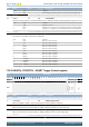
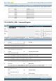
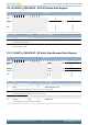
17.5.3 USARTn_TRIGCTRL - USART Trigger Control register
Offset Bit Position
0x008
31
30
29
28
27
26
25
24
23
22
21
20
19
18
17
16
15
14
13
12
11
10
9
8
7
6
5
4
3
2
1
0
Reset
0
0
0
0x0
Access
RW
RW
RW
RW
Name
AUTOTXTEN
TXTEN
RXTEN
TSEL
Bit Name Reset Access Description
31:7 Reserved
To ensure compatibility with future devices, always write bits to 0. More information in Section 2.1 (p. 3)
6 AUTOTXTEN 0 RW AUTOTX Trigger Enable
When set, AUTOTX is enabled as long as the PRS channel selected by TSEL has a high value
5 TXTEN 0 RW Transmit Trigger Enable
When set, the PRS channel selected by TSEL sets TXEN, enabling the transmitter on positive trigger edges.
4 RXTEN 0 RW Receive Trigger Enable
When set, the PRS channel selected by TSEL sets RXEN, enabling the receiver on positive trigger edges.
3 Reserved
To ensure compatibility with future devices, always write bits to 0. More information in Section 2.1 (p. 3)
2:0 TSEL 0x0 RW Trigger PRS Channel Select