
User manual


...the world's most energy friendly microcontrollers
2012-04-24 - Giant Gecko Family - d0053_Rev0.96 474
www.energymicro.com
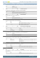
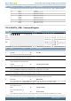
Bit Name Reset Access Description
Value Mode Description
1 X8 Double speed with 8X oversampling in asynchronous mode
2 X6 6X oversampling in asynchronous mode
3 X4 Quadruple speed with 4X oversampling in asynchronous mode
4 MPAB 0 RW Multi-Processor Address-Bit
Defines the value of the multi-processor address bit. An incoming frame with its 9th bit equal to the value of this bit marks the frame
as a multi-processor address frame.
3 MPM 0 RW Multi-Processor Mode
Multi-processor mode uses the 9th bit of the USART frames to tell whether the frame is an address frame or a data frame.
Value Description
0 The 9th bit of incoming frames has no special function
1 An incoming frame with the 9th bit equal to MPAB will be loaded into the receive buffer regardless of RXBLOCK and
will result in the MPAB interrupt flag being set
2 CCEN 0 RW Collision Check Enable
Enables collision checking on data when operating in half duplex modus.
Value Description
0 Collision check is disabled
1 Collision check is enabled. The receiver must be enabled for the check to be performed
1 LOOPBK 0 RW Loopback Enable
Allows the receiver to be connected directly to the USART transmitter for loopback and half duplex communication.
Value Description
0 The receiver is connected to and receives data from U(S)n_RX
1 The receiver is connected to and receives data from U(S)n_TX
0 SYNC 0 RW USART Synchronous Mode
Determines whether the USART is operating in asynchronous or synchronous mode.
Value Description
0 The USART operates in asynchronous mode
1 The USART operates in synchronous mode
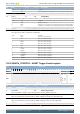
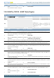
17.5.2 USARTn_FRAME - USART Frame Format Register
Offset Bit Position
0x004
31
30
29
28
27
26
25
24
23
22
21
20
19
18
17
16
15
14
13
12
11
10
9
8
7
6
5
4
3
2
1
0
Reset
0x1
0x0
0x5
Access
RW
RW
RW
Name
STOPBITS
PARITY
DATABITS
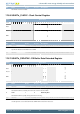
Bit Name Reset Access Description
31:14 Reserved
To ensure compatibility with future devices, always write bits to 0. More information in Section 2.1 (p. 3)
13:12 STOPBITS 0x1 RW Stop-Bit Mode
Determines the number of stop-bits used.
Value Mode Description
0 HALF The transmitter generates a half stop bit. Stop-bits are not verified by receiver
1 ONE One stop bit is generated and verified
2 ONEANDAHALF The transmitter generates one and a half stop bit. The receiver verifies the first stop bit