
User manual


...the world's most energy friendly microcontrollers
2012-04-24 - Giant Gecko Family - d0053_Rev0.96 473
www.energymicro.com
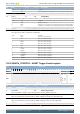
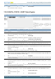
Bit Name Reset Access Description
Default value is active low. This affects both the selection of external slaves, as well as the selection of the microcontroller as a slave.
Value Description
0 Chip select is active low
1 Chip select is active high
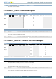
14 TXINV 0 RW Transmitter output Invert
The output from the USART transmitter can optionally be inverted by setting this bit.
Value Description
0 Output from the transmitter is passed unchanged to U(S)n_TX
1 Output from the transmitter is inverted before it is passed to U(S)n_TX
13 RXINV 0 RW Receiver Input Invert
Setting this bit will invert the input to the USART receiver.
Value Description
0 Input is passed directly to the receiver
1 Input is inverted before it is passed to the receiver
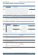
12 TXBIL 0 RW TX Buffer Interrupt Level
Determines the interrupt and status level of the transmit buffer.
Value Mode Description
0 EMPTY TXBL and the TXBL interrupt flag are set when the transmit buffer becomes empty.
TXBL is cleared when the buffer becomes nonempty.
1 HALFFULL TXBL and TXBLIF are set when the transmit buffer goes from full to half-full or empty.
TXBL is cleared when the buffer becomes full.
11 CSMA 0 RW Action On Slave-Select In Master Mode
This register determines the action to be performed when slave-select is configured as an input and driven low while in master mode.
Value Mode Description
0 NOACTION No action taken
1 GOTOSLAVEMODE Go to slave mode
10 MSBF 0 RW Most Significant Bit First
Decides whether data is sent with the least significant bit first, or the most significant bit first.
Value Description
0 Data is sent with the least significant bit first
1 Data is sent with the most significant bit first
9 CLKPHA 0 RW Clock Edge For Setup/Sample
Determines where data is set-up and sampled according to the bus clock when in synchronous mode.
Value Mode Description
0 SAMPLELEADING Data is sampled on the leading edge and set-up on the trailing edge of the bus clock
in synchronous mode
1 SAMPLETRAILING Data is set-up on the leading edge and sampled on the trailing edge of the bus clock
in synchronous mode
8 CLKPOL 0 RW Clock Polarity
Determines the clock polarity of the bus clock used in synchronous mode.
Value Mode Description
0 IDLELOW The bus clock used in synchronous mode has a low base value
1 IDLEHIGH The bus clock used in synchronous mode has a high base value
7 Reserved
To ensure compatibility with future devices, always write bits to 0. More information in Section 2.1 (p. 3)
6:5 OVS 0x0 RW Oversampling
Sets the number of clock periods in a UART bit-period. More clock cycles gives better robustness, while less clock cycles gives
better performance.
Value Mode Description
0 X16 Regular UART mode with 16X oversampling in asynchronous mode