
User manual

...the world's most energy friendly microcontrollers
2012-04-24 - Giant Gecko Family - d0053_Rev0.96 470
www.energymicro.com
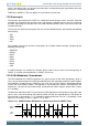
The IrDA module is enabled by setting IREN. The USART transmitter output and receiver input is then
routed through the IrDA modulator.
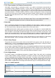
The width of the pulses generated by the IrDA modulator is set by configuring IRPW in
USARTn_IRCTRL. Four pulse widths are available, each defined relative to the configured bit period
as listed in Table 17.10 (p. 470) .
Table 17.10. USART IrDA Pulse Widths
IRPW Pulse width OVS=0 Pulse width OVS=1 Pulse width OVS=2 Pulse width OVS=3
00 1/16 1/8 1/6 1/4
01 2/16 2/8 2/6 N/A
10 3/16 3/8 N/A N/A
11 4/16 N/A N/A N/A
By default, no filter is enabled in the IrDA demodulator. A filter can be enabled by setting IRFILT in
USARTn_IRCTRL. When the filter is enabled, an incoming pulse has to last for 4 consecutive clock
cycles to be detected by the IrDA demodulator.
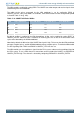
Note that by default, the idle value of the USART data signal is high. This means that the IrDA modulator
generates negative pulses, and the IrDA demodulator expects negative pulses. To make the IrDA module
use RZI signalling, both TXINV and RXINV in USARTn_CTRL must be set.
The IrDA module can also modulate a signal from the PRS system, and transmit a modulated signal to
the PRS system. To use a PRS channel as transmitter source instead of the USART, set IRPRSEN in
USARTn_IRCTRL high. The channel is selected by configuring IRPRSSEL in USARTn_IRCTRL.