
User manual

...the world's most energy friendly microcontrollers
2012-04-24 - Giant Gecko Family - d0053_Rev0.96 469
www.energymicro.com
and it is possible to make sure that the transmitter does not begin driving the output before the frame
on the bus is completely transmitted.
TXDELAY in USARTn_CTRL only applies to asynchronous transmission.
17.3.8 Interrupts
The interrupts generated by the USART are combined into two interrupt vectors. Interrupts related to
reception are assigned to one interrupt vector, and interrupts related to transmission are assigned to
the other. Separating the interrupts in this way allows different priorities to be set for transmission and
reception interrupts.
The transmission interrupt vector groups the transmission-related interrupts generated by the following
interrupt flags:
• TXC
• TXBL
• TXOF
• CCF
The reception interrupt on the other hand groups the reception-related interrupts, triggered by the
following interrupt flags:
• RXDATAV
• RXFULL
• RXOF
• RXUF
• PERR
• FERR
• MPAF
• SSM
If USART interrupts are enabled, an interrupt will be made if one or more of the interrupt flags in
USART_IF and their corresponding bits in USART_IEN are set.
17.3.9 IrDA Modulator/ Demodulator
The IrDA modulator on USART0 implements the physical layer of the IrDA specification, which is
necessary for communication over IrDA. The modulator takes the signal output from the USART module,
and modulates it before it leaves USART0. In the same way, the input signal is demodulated before
it enters the actual USART module. The modulator is only available on USART0, and implemetns the
original Rev. 1.0 physical layer and one high speed extension which supports speeds from 2.4 kbps
to 1.152 Mbps.
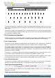
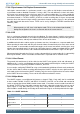
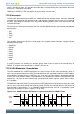
The data from and to the USART is represented in a NRZ (Non Return to Zero) format, where the signal
value is at the same level through the entire bit period. For IrDA, the required format is RZI (Return to
Zero Inverted), a format where a “1” is signalled by holding the line low, and a “0” is signalled by a short
high pulse. An example is given in Figure 17.21 (p. 469) .
Figure 17.21. USART Example RZI Signal for a given Asynchronous USART Frame
S 0
1 2
3
4 5
6 7
P
Stop
IdleIdle
USART
(NRZ)
IrDA
(RZI)