
User manual

...the world's most energy friendly microcontrollers
2012-04-24 - Giant Gecko Family - d0053_Rev0.96 449
www.energymicro.com
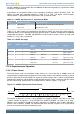
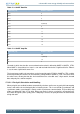
Table 17.3. USART Data Bits
DATA BITS [3:0] Number of Data bits
0001 4
0010 5
0011 6
0100 7
0101 8 (Default)
0110 9
0111 10
1000 11
1001 12
1010 13
1011 14
1100 15
1101 16
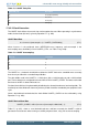
Table 17.4. USART Stop Bits
STOP BITS [1:0] Number of Stop bits
00 0.5
01 1 (Default)
10 1.5
11 2
The order in which the data bits are transmitted and received is defined by MSBF in USARTn_CTRL.
When MSBF is cleared, data in a frame is sent and received with the least significant bit first. When it
is set, the most significant bit comes first.
The frame format used by the transmitter can be inverted by setting TXINV in USARTn_CTRL, and the
format expected by the receiver can be inverted by setting RXINV in USARTn_CTRL. These bits affect
the entire frame, not only the data bits. An inverted frame has a low idle state, a high start-bit, inverted
data and parity bits, and low stop-bits.
17.3.2.1.1 Parity bit Calculation and Handling
When parity bits are enabled, hardware automatically calculates and inserts any parity bits into outgoing
frames, and verifies the received parity bits in incoming frames. This is true for both asynchronous and
synchronous modes, even though it is mostly used in asynchronous communication. The possible parity
modes are defined in Table 17.5 (p. 450) . When even parity is chosen, a parity bit is inserted to make
the number of high bits (data + parity) even. If odd parity is chosen, the parity bit makes the total number
of high bits odd.