
User manual

...the world's most energy friendly microcontrollers
2012-04-24 - Giant Gecko Family - d0053_Rev0.96 448
www.energymicro.com
possible, additional synchronization bits are added to the data when operating in asynchronous mode,
resulting in a slight overhead.
Asynchronous or synchronous mode can be selected by configuring SYNC in USARTn_CTRL. The
options are listed with supported protocols in Table 17.1 (p. 448) . Full duplex and half duplex
communication is supported in both asynchronous and synchronous mode.
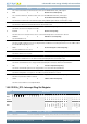
Table 17.1. USART Asynchronous vs. Synchronous Mode
SYNC Communication Mode Supported Protocols
0 Asynchronous RS-232, RS-485 (w/external driver), IrDA, ISO 7816
1 Synchronous SPI, MicroWire, 3-wire
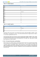
Table 17.2 (p. 448) explains the functionality of the different USART pins when the USART operates
in different modes. Pin functionality enclosed in square brackets is optional, and depends on additional
configuration parameters. LOOPBK and MASTER are discussed in Section 17.3.2.5 (p. 456) and
Section 17.3.3.3 (p. 463) respectively.
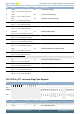
Table 17.2. USART Pin Usage
Pin functionality
SYNC LOOPBK MASTER
U(S)n_TX
(MOSI)
U(S)n_RX (MISO) USn_CLK USn_CS
0 0 x Data out Data in - [Driver enable]
1 1 x Data out/in - - [Driver enable]
1 0 0 Data in Data out Clock in Slave select
1 0 1 Data out Data in Clock out [Auto slave select]
1 1 0 Data out/in - Clock in Slave select
1 1 1 Data out/in - Clock out [Auto slave select]
17.3.2 Asynchronous Operation
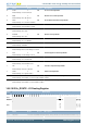
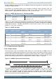
17.3.2.1 Frame Format
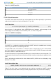
The frame format used in asynchronous mode consists of a set of data bits in addition to bits for
synchronization and optionally a parity bit for error checking. A frame starts with one start-bit (S), where
the line is driven low for one bit-period. This signals the start of a frame, and is used for synchronization.
Following the start bit are 4 to 16 data bits and an optional parity bit. Finally, a number of stop-bits, where
the line is driven high, end the frame. An example frame is shown in Figure 17.2 (p. 448) .
Figure 17.2. USART Asynchronous Frame Format
S 0
1 2
3
4 [5]
[6] [7]
[8]
[P]
Stop
Start or idleStop or idle
Fram e
The number of data bits in a frame is set by DATABITS in USARTn_FRAME, see Table 17.3 (p. 449)
, and the number of stop-bits is set by STOPBITS in USARTn_FRAME, see Table 17.4 (p. 449) .
Whether or not a parity bit should be included, and whether it should be even or odd is defined by
PARITY, also in USARTn_FRAME. For communication to be possible, all parties of an asynchronous
transfer must agree on the frame format being used.