
User manual

...the world's most energy friendly microcontrollers
2012-04-24 - Giant Gecko Family - d0053_Rev0.96 447
www.energymicro.com
• Configurable number of data bits, 4-16 (plus the parity bit, if enabled)
• HW parity bit generation and check
• Configurable number of stop bits in asynchronous mode: 0.5, 1, 1.5, 2
• HW collision detection
• Multi-processor mode
• IrDA modulator on USART0
• SmartCard (ISO7816) mode
• I2S mode
• Separate interrupt vectors for receive and transmit interrupts
• Loopback mode
• Half duplex communication
• Communication debugging
• PRS RX input
17.3 Functional Description
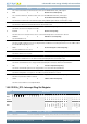
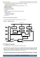
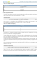
An overview of the USART module is shown in Figure 17.1 (p. 447) .
Figure 17.1. USART Overview
TX Buffer
(2-level FIFO)
TX Shift Register
U(S)n_TX
RX Buffer
(2-level FIFO)
RX Shift Register
UART Control
and status
Peripheral Bus
Baud rate
generator
USn_CLK
Pin
ctrl
USn_CS
U(S)n_RX
IrDA
modulator
IrDA
dem odulator
!RXBLOCK
PRS inputs
17.3.1 Modes of Operation
The USART operates in either asynchronous or synchronous mode.
In synchronous mode, a separate clock signal is transmitted with the data. This clock signal is generated
by the bus master, and both the master and slave sample and transmit data according to this clock.
Both master and slave modes are supported by the USART. The synchronous communication mode is
compatible with the Serial Peripheral Interface Bus (SPI) standard.
In asynchronous mode, no separate clock signal is transmitted with the data on the bus. The USART
receiver thus has to determine where to sample the data on the bus from the actual data. To make this