
User manual


...the world's most energy friendly microcontrollers
2012-04-24 - Giant Gecko Family - d0053_Rev0.96 435
www.energymicro.com
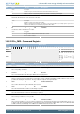
Bit Name Reset Access Description
When set, the bus automatically goes idle on a bus idle timeout, allowing new transfers to be initiated.
Value Description
0 A bus idle timeout has no effect on the bus state.
1 A bus idle timeout tells the I
2
C module that the bus is idle, allowing new transfers to be initiated.
14 Reserved
To ensure compatibility with future devices, always write bits to 0. More information in Section 2.1 (p. 3)
13:12 BITO 0x0 RW Bus Idle Timeout
Use to generate a timeout when SCL has been high for a given amount time between a START and STOP condition. When in a
bus transaction, i.e. the BUSY flag is set, a timer is started whenever SCL goes high. When the timer reaches the value defined
by BITO, it sets the BITO interrupt flag. The BITO interrupt flag will then be set periodically as long as SCL remains high. The bus
idle timeout is active as long as BUSY is set. It is thus stopped automatically on a timeout if GIBITO is set. It is also stopped a
STOP condition is detected and when the ABORT command is issued. The timeout is activated whenever the bus goes BUSY, i.e.
a START condition is detected.
Value Mode Description
0 OFF Timeout disabled
1 40PCC Timeout after 40 prescaled clock cycles. In standard mode at 100 kHz, this results in
a 50us timeout.
2 80PCC Timeout after 80 prescaled clock cycles. In standard mode at 100 kHz, this results in
a 100us timeout.
3 160PCC Timeout after 160 prescaled clock cycles. In standard mode at 100 kHz, this results
in a 200us timeout.
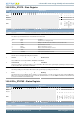
11:10 Reserved
To ensure compatibility with future devices, always write bits to 0. More information in Section 2.1 (p. 3)
9:8 CLHR 0x0 RW Clock Low High Ratio
Determines the ratio between the low and high parts of the clock signal generated on SCL as master.
Value Mode Description
0 STANDARD The ratio is 4:4. Both low and high periods lasts 4 prescaled clock cycles
1 ASYMMETRIC The ratio is 6:3. Low period lasts 6 and high period lasts 4 prescaled clock cycles
2 FAST The ratio is 14:9. Low period lasts 16 and high period lasts 9 prescaled clock cycles
7 Reserved
To ensure compatibility with future devices, always write bits to 0. More information in Section 2.1 (p. 3)
6 GCAMEN 0 RW General Call Address Match Enable
Set to enable address match on general call in addition to the programmed slave address.
Value Description
0 General call address will be NACK'ed if it is not included by the slave address and address mask.
1 When a general call address is received, a software response is required.
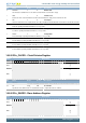
5 ARBDIS 0 RW Arbitration Disable
A master or slave will not release the bus upon losing arbitration.
Value Description
0 When a device loses arbitration, the ARB interrupt flag is set and the bus is released.
1 When a device loses arbitration, the ARB interrupt flag is set, but communication proceeds.
4 AUTOSN 0 RW Automatic STOP on NACK
Write to 1 to make a master transmitter send a STOP when a NACK is received from a slave.
Value Description
0 Stop is not automatically sent if a NACK is received from a slave.
1 The master automatically sends a STOP if a NACK is received from a slave.
3 AUTOSE 0 RW Automatic STOP when Empty
Write to 1 to make a master transmitter send a STOP when no more data is available for transmission.
Value Description
0 A stop must be sent manually when no more data is to be transmitted.
1 The master automatically sends a STOP when no more data is available for transmission.
2 AUTOACK 0 RW Automatic Acknowledge
Set to enable automatic acknowledges.