
User manual


...the world's most energy friendly microcontrollers
2012-04-24 - Giant Gecko Family - d0053_Rev0.96 42
www.energymicro.com
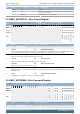
Bit Name Reset Access Description
12 CLEARWDATA 0 W1 Clear WDATA state
Will set WDATAREADY and DMA request. Should only be used when no write is active.
11:10 Reserved
To ensure compatibility with future devices, always write bits to 0. More information in Section 2.1 (p. 3)
9 ERASEMAIN1 0 W1 Mass erase region 1
Initiate mass erase of region 1. For devices supporting read-while-write, this is the upper half of the flash. Before use
MSC_MASSLOCK must be unlocked. To completely prevent access from software, clear bit 1 in the mass erase lock-word (MLW)
8 ERASEMAIN0 0 W1 Mass erase region 0
Initiate mass erase of region 0. For devices supporting read-while-write, this is the lower half of the flash. For other devices it is the
entire flash. Before use MSC_MASSLOCK must be unlocked. To completely prevent access from software, clear bit 0 in the mass
erase lock-word (MLW)
7:6 Reserved
To ensure compatibility with future devices, always write bits to 0. More information in Section 2.1 (p. 3)
5 ERASEABORT 0 W1 Abort erase sequence
Writing to this bit will abort an ongoing erase sequence.
4 WRITETRIG 0 W1 Word Write Sequence Trigger
Start write of the first word written to MSC_WDATA, then add 4 to ADDR and write the next word if available within a 30us timeout.
When ADDR is incremented past the page boundary, ADDR is set to the base of the page. If WDOUBLE is set, two words are
required every time, and ADDR is incremented by 8.
3 WRITEONCE 0 W1 Word Write-Once Trigger
Write the word in MSC_WDATA to ADDR. Flash access is returned to the AHB interface as soon as the write operation completes.
The WREN bit in the MSC_WRITECTRL register must be set in order to use this command.
2 WRITEEND 0 W1 End Write Mode
Write 1 to end write mode when using the WRITETRIG command.
1 ERASEPAGE 0 W1 Erase Page
Erase any user defined page selected by the MSC_ADDRB register. The WREN bit in the MSC_WRITECTRL register must be set
in order to use this command.
0 LADDRIM 0 W1 Load MSC_ADDRB into ADDR
Load the internal write address register ADDR from the MSC_ADDRB register. The internal address register ADDR is incremented
automatically by 4 after each word is written. When ADDR is incremented past the page boundary, ADDR is set to the base of the page.
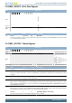
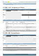
7.5.5 MSC_ADDRB - Page Erase/Write Address Buffer
Offset Bit Position
0x010
31
30
29
28
27
26
25
24
23
22
21
20
19
18
17
16
15
14
13
12
11
10
9
8
7
6
5
4
3
2
1
0
Reset
0x00000000
Access
RW
Name
ADDRB
Bit Name Reset Access Description
31:0 ADDRB 0x00000000 RW Page Erase or Write Address Buffer
This register holds the page address for the erase or write operation. This register is loaded into the internal MSC_ADDR register
when the LADDRIM field in MSC_CMD is set. The MSC_ADDR register is not readable.