
User manual

...the world's most energy friendly microcontrollers
2012-04-24 - Giant Gecko Family - d0053_Rev0.96 400
www.energymicro.com
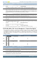
Bit Name Reset Access Description
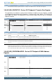
31:0 DOEP0DMAADDR 0xXXXXXXXX RW DMA Address
Holds the start address of the external memory for storing endpoint data. For control endpoints, this field stores control OUT data
packets as well as SETUP transaction data packets. When more than three SETUP packets are received back-to-back, the SETUP
data packet in the memory is overwritten. This register is incremented on every AHB transaction. The application can give only a
DWORD-aligned address. The data for this register field is stored in RAM. Thus, the reset value is undefined (X).
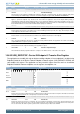
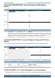
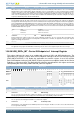
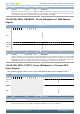
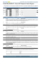
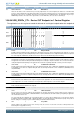
15.6.64 USB_DOEPx_CTL - Device OUT Endpoint x+1 Control Register
The application uses this register to control the behavior of each logical endpoint other than endpoint 0.
Offset Bit Position
0x3CB20
31
30
29
28
27
26
25
24
23
22
21
20
19
18
17
16
15
14
13
12
11
10
9
8
7
6
5
4
3
2
1
0
Reset
0
0
0
0
0
0
0
0
0x0
0
0
0
0x000
Access
RW1
RW1
W1
W1
W1
W1
RW1
RW
RW
R
R
RW
RW
Name
EPENA
EPDIS
SETD1PIDOF
SETD0PIDEF
SNAK
CNAK
STALL
SNP
EPTYPE
NAKSTS
DPIDEOF
USBACTEP
MPS
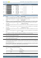
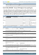
Bit Name Reset Access Description
31 EPENA 0 RW1 Endpoint Enable
In DMA mode this bit indicates that the application has allocated the memory to start receiving data from the USB. The core clears
this bit before setting any of the following interrupts on this endpoint: SETUP Phase Done, Endpoint Disabled, Transfer Completed.
For control endpoints in DMA mode, this bit must be set to be able to transfer SETUP data packets in memory.
30 EPDIS 0 RW1 Endpoint Disable
The application sets this bit to stop transmitting/receiving data on an endpoint, even before the transfer for that endpoint is complete.
The application must wait for the Endpoint Disabled interrupt before treating the endpoint as disabled. The core clears this bit before
setting the Endpoint Disabled interrupt. The application must set this bit only if Endpoint Enable is already set for this endpoint.
29 SETD1PIDOF 0 W1 Set DATA1 PID / Odd Frame
For bulk and interrupt endpoints writing this field sets the Endpoint Data PID / Even or Odd Frame (DPIDEOF) field in this register
to DATA1ODD. For isochronous endpoints writing this field sets the Endpoint Data PID / Even or Odd Frame (DPIDEOF) field to
odd (DATA1ODD).
28 SETD0PIDEF 0 W1 Set DATA0 PID / Even Frame
For bulk and interrupt endpoints writing this field sets the Endpoint Data PID / Even or Odd Frame (DPIDEOF) field in this register
to DATA0EVEN. For isochronous endpoints writing this field sets the Endpoint Data PID / Even or Odd Frame (DPIDEOF) field to
odd (DATA0EVEN).
27 SNAK 0 W1 Set NAK
A write to this bit sets the NAK bit for the endpoint. Using this bit, the application can control the transmission of NAK handshakes
on an endpoint. The core can also set this bit for an endpoint after a SETUP packet is received on that endpoint.
26 CNAK 0 W1 Clear NAK
A write to this bit clears the NAK bit for the endpoint.
25:22 Reserved
To ensure compatibility with future devices, always write bits to 0. More information in Section 2.1 (p. 3)
21 STALL 0 RW1 STALL Handshake
For non-control, non-isochronous endpoints: The application sets this bit to stall all tokens from the USB host to this endpoint. If a
NAK bit, Global Non-periodic IN NAK, or Global OUT NAK is set along with this bit, the STALL bit takes priority. Only the application
can clear this bit, never the core.
For control endpoints: The application can only set this bit, and the core clears it, when a SETUP token is received for this endpoint.
If a NAK bit, Global Non-periodic IN NAK, or Global OUT NAK is set along with this bit, the STALL bit takes priority. Irrespective of
this bit's setting, the core always responds to SETUP data packets with an ACK handshake.
20 SNP 0 RW Snoop Mode
This bit configures the endpoint to Snoop mode. In Snoop mode, the core does not check the correctness of OUT packets before
transferring them to application memory.