
User manual

...the world's most energy friendly microcontrollers
2012-04-24 - Giant Gecko Family - d0053_Rev0.96 394
www.energymicro.com
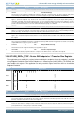
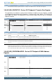
Bit Name Reset Access Description
When this bit is 0 the core is transmitting non-NAK handshakes based on the FIFO status. When this bit is 1 the core is transmitting
NAK handshakes on this endpoint. When either the application or the core sets this bit the core stops receiving any data on an OUT
endpoint, even if there is space in the RxFIFO to accommodate the incoming packet. For non-isochronous IN endpoints the core
stops transmitting any data on an IN endpoint, even if there data is available in the TxFIFO. For isochronous IN endpoints the core
sends out a zero-length data packet, even if there data is available in the TxFIFO. Irrespective of this bit's setting, the core always
responds to SETUP data packets with an ACK handshake.
16 DPIDEOF 0 R Endpoint Data PID / Even or Odd Frame
For interrupt/bulk endpoints this field contains the PID of the packet to be received or transmitted on this endpoint. The application
must program the PID of the first packet to be received or transmitted on this endpoint, after the endpoint is activated. The applications
use the SETD1PIDOF and SETD0PIDEF fields of this register to program either DATA0 or DATA1 PID. For isochronous endpoints,
this field indicates the frame number in which the core transmits/receives isochronous data for this endpoint. The application must
program the even/odd frame number in which it intends to transmit/receive isochronous data for this endpoint using the SETD0PIDEF
and SETD1PIDOF fields in this register.
Value Mode Description
0 DATA0EVEN DATA0 PID / Even Frame.
1 DATA1ODD DATA1 PID / Odd Frame.
15 USBACTEP 0 RW USB Active Endpoint
Indicates whether this endpoint is active in the current configuration and interface. The core clears this bit for all endpoints after
detecting a USB reset. After receiving the SetConfiguration and SetInterface commands, the application must program endpoint
registers accordingly and set this bit.
14:11 Reserved
To ensure compatibility with future devices, always write bits to 0. More information in Section 2.1 (p. 3)
10:0 MPS 0x000 RW Maximum Packet Size
The application must program this field with the maximum packet size for the current logical endpoint. This value is in bytes.
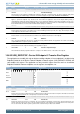
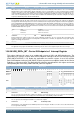
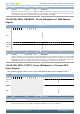
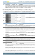
15.6.56 USB_DIEPx_INT - Device IN Endpoint x+1 Interrupt Register
This register indicates the status of an endpoint with respect to USB- and AHB-related events. The
application must read this register when the IN Endpoints Interrupt bit of the Core Interrupt register
(USB_GINTSTS.IEPINT) is set. Before the application can read this register, it must first read the
Device All Endpoints Interrupt (USB_DAINT) register to get the exact endpoint number for the Device
Endpoint x+1 Interrupt register. The application must clear the appropriate bit in this register to clear the
corresponding bits in the USB_DAINT and USB_GINTSTS registers.
Offset Bit Position
0x3C928
31
30
29
28
27
26
25
24
23
22
21
20
19
18
17
16
15
14
13
12
11
10
9
8
7
6
5
4
3
2
1
0
Reset
0
0
0
1
0
0
0
0
0
0
Access
RW1
RW1
RW1
R
RW1
RW1
RW1
RW1
RW1
RW1
Name
NAKINTRPT
BBLEERR
PKTDRPSTS
TXFEMP
INEPNAKEFF
INTKNTXFEMP
TIMEOUT
AHBERR
EPDISBLD
XFERCOMPL
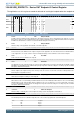
Bit Name Reset Access Description
31:14 Reserved
To ensure compatibility with future devices, always write bits to 0. More information in Section 2.1 (p. 3)
13 NAKINTRPT 0 RW1 NAK Interrupt
The core generates this interrupt when a NAK is transmitted or received by the device. In case of isochronous IN endpoints the
interrupt gets generated when a zero length packet is transmitted due to un-availability of data in the TXFifo.
12 BBLEERR 0 RW1 NAK Interrupt
The core generates this interrupt when babble is received for the endpoint.
11 PKTDRPSTS 0 RW1 Packet Drop Status
This bit indicates to the application that an ISO OUT packet has been dropped. This bit does not have an associated mask bit and
does not generate an interrupt.