
User manual

...the world's most energy friendly microcontrollers
2012-04-24 - Giant Gecko Family - d0053_Rev0.96 391
www.energymicro.com
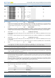
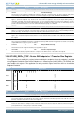
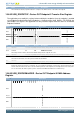
Bit Name Reset Access Description
10:8 Reserved
To ensure compatibility with future devices, always write bits to 0. More information in Section 2.1 (p. 3)
7 TXFEMP 1 R Transmit FIFO Empty
This interrupt is asserted when the TxFIFO for this endpoint is either half or completely empty. The half or completely empty status
is determined by the TxFIFO Empty Level bit in the Core AHB Configuration register (USB_GAHBCFG.NPTXFEMPLVL).
6 INEPNAKEFF 0 RW1 IN Endpoint NAK Effective
Applies to periodic IN endpoints only. This bit can be cleared when the application clears the IN endpoint NAK by writing to
USB_DIEP0CTL.CNAK. This interrupt indicates that the core has sampled the NAK bit set (either by the application or by the core).
The interrupt indicates that the IN endpoint NAK bit set by the application has taken effect in the core. This interrupt does not guarantee
that a NAK handshake is sent on the USB. A STALL bit takes priority over a NAK bit.
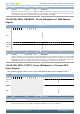
5 Reserved
To ensure compatibility with future devices, always write bits to 0. More information in Section 2.1 (p. 3)
4 INTKNTXFEMP 0 RW1 IN Token Received When TxFIFO is Empty
Indicates that an IN token was received when the associated TxFIFO (periodic/non-periodic) was empty. This interrupt is asserted
on the endpoint for which the IN token was received.
3 TIMEOUT 0 RW1 Timeout Condition
Indicates that the core has detected a timeout condition on the USB for the last IN token on this endpoint.
2 AHBERR 0 RW1 AHB Error
This is generated in DMA mode when there is an AHB error during an AHB read/write. The application can read the corresponding
endpoint DMA address register to get the error address.
1 EPDISBLD 0 RW1 Endpoint Disabled Interrupt
This bit indicates that the endpoint is disabled per the application's request.
0 XFERCOMPL 0 RW1 Transfer Completed Interrupt
This field indicates that the programmed transfer is complete on the AHB as well as on the USB, for this endpoint.
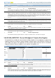
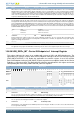
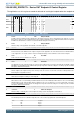
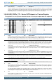
15.6.52 USB_DIEP0TSIZ - Device IN Endpoint 0 Transfer Size Register
The application must modify this register before enabling endpoint 0. Once endpoint 0 is enabled using
Endpoint Enable bit of the Device Control Endpoint 0 Control register (USB_DIEP0CTL.EPENA), the
core modifies this register. The application can only read this register once the core has cleared the
Endpoint Enable bit. Nonzero endpoints use the registers for endpoints 1-6.
Offset Bit Position
0x3C910
31
30
29
28
27
26
25
24
23
22
21
20
19
18
17
16
15
14
13
12
11
10
9
8
7
6
5
4
3
2
1
0
Reset
0x0
0x00
Access
RW
RW
Name
PKTCNT
XFERSIZE
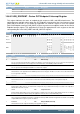
Bit Name Reset Access Description
31:21 Reserved
To ensure compatibility with future devices, always write bits to 0. More information in Section 2.1 (p. 3)
20:19 PKTCNT 0x0 RW Packet Count
Indicates the total number of USB packets that constitute the Transfer Size amount of data for endpoint 0. This field is decremented
every time a packet (maximum size or short packet) is read from the TxFIFO.
18:7 Reserved
To ensure compatibility with future devices, always write bits to 0. More information in Section 2.1 (p. 3)
6:0 XFERSIZE 0x00 RW Transfer Size
Indicates the transfer size in bytes for endpoint 0. The core interrupts the application only after it has exhausted the transfer size
amount of data. The transfer size can be set to the maximum packet size of the endpoint, to be interrupted at the end of each packet.
The core decrements this field every time a packet from the external memory is written to the TxFIFO.