
User manual

...the world's most energy friendly microcontrollers
2012-04-24 - Giant Gecko Family - d0053_Rev0.96 377
www.energymicro.com
Bit Name Reset Access Description
The core sets this bit when a device connection is detected to trigger an interrupt to the application using the Host Port Interrupt bit of
the Core Interrupt register (USB_GINTSTS.PRTINT). This bit can be set only by the core and the application should write 1 to clear
it. The application must write a 1 to this bit to clear the interrupt.
0 PRTCONNSTS 0 R Port Connect Status
When this bit is 1 a device is attached to the port.
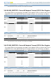
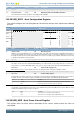
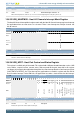
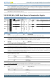
15.6.35 USB_HCx_CHAR - Host Channel x Characteristics Register
Offset Bit Position
0x3C500
31
30
29
28
27
26
25
24
23
22
21
20
19
18
17
16
15
14
13
12
11
10
9
8
7
6
5
4
3
2
1
0
Reset
0
0
0
0x00
0x0
0x0
0
0
0x0
0x000
Access
RW1
RW1
RW
RW
RW
RW
RW
RW
RW
RW
Name
CHENA
CHDIS
ODDFRM
DEVADDR
MC
EPTYPE
LSPDDEV
EPDIR
EPNUM
MPS
Bit Name Reset Access Description
31 CHENA 0 RW1 Channel Enable
This field is set by the application and cleared by the core. The state of this bit reflects the channel enable status.
30 CHDIS 0 RW1 Channel Disable
The application sets this bit to stop transmitting/receiving data on a channel, even before the transfer for that channel is complete.
The application must wait for the Channel Disabled interrupt before treating the channel as disabled.
29 ODDFRM 0 RW Odd Frame
This field is set (reset) by the application to indicate that the OTG host must perform a transfer in an odd frame. This field is applicable
for only periodic (isochronous and interrupt) transactions.
28:22 DEVADDR 0x00 RW Device Address
This field selects the specific device serving as the data source or sink.
21:20 MC 0x0 RW Multi Count
For periodic transfers this field indicates to the host the number of transactions that must be executed per frame for this periodic
endpoint. For non-periodic transfers, this field is used only in DMA mode, and specifies the number packets to be fetched for this
channel before the internal DMA engine changes arbitration.
19:18 EPTYPE 0x0 RW Endpoint Type
Indicates the transfer type selected.
Value Mode Description
0 CONTROL Control endpoint.
1 ISO Isochronous endpoint.
2 BULK Bulk endpoint.
3 INT Interrupt endpoint.
17 LSPDDEV 0 RW Low-Speed Device
This field is set by the application to indicate that this channel is communicating to a low-speed device.
16 Reserved
To ensure compatibility with future devices, always write bits to 0. More information in Section 2.1 (p. 3)
15 EPDIR 0 RW Endpoint Direction
Indicates whether the transaction is IN or OUT.
Value Mode Description
0 OUT Direction is OUT.
1 IN Direction is IN.