
User manual

...the world's most energy friendly microcontrollers
2012-04-24 - Giant Gecko Family - d0053_Rev0.96 37
www.energymicro.com
cache misses occur inside the interrupt routine. So, for example, if a cached function is called from the
interrupt routine, the instructions for that function will be taken from the cache.
The cache content is not retained in EM2, EM3 and EM4. The cache is therefore invalidated regardless
of the setting of AIDIS in MSC_READCTRL when entering these energy modes. Applications that switch
frequently between EM0 and EM2/3 and executes the very same non-looping code almost every time
will most likely benefit from putting this code in RAM. The interrupt vectors can also be put in RAM to
reduce current consumption even further.
The cache also supports caching of instruction fetches from the external bus interface (EBI) when
accessing the EBI through code space. By default, this is enabled, but it can be disabled by setting
EBICDIS in MSC_READCTRL.
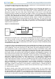
7.3.5.7 Instruction Prefetch
The MSC also includes instruction prefetch capability for the internal flash memory. This feature is by
default disabled, but can be enabled by setting setting PREFETCH in MSC_READCTRL. The prefetcher
works by the assumption that the next instruction word will be needed in the next fetch. This next word
is fetched before the word is actually needed. If it turns out that this next word is actually needed by
the CPU, the prefetched word can be returned in one clock cycle, removing the wait-states that would
otherwise potentially be needed by a flash read. With the prefetcher enabled, the number of waitstates
to the flash when accessing code that is not in the cache is effectively halved.
7.3.6 Erase and Write Operations
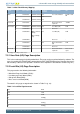
The AUXHFRCO is used for timing during flash write and erase operations. To achieve correct timing,
the MSC_TIMEBASE register has to be configured according to the settings in CMU_AUXHFRCOCTRL.
BASE in MSC_TIMEBASE defines how many AUXCLK cycles - 1 there is in 1 us or 5 us, depending
on the configuration of PERIOD. To ensure that timing of flash write and erase operations is within the
specification of the flash, the value written to BASE should give at least a 10% margin with respect to
the period, i.e. for the 1 us PERIOD, the number of cycles should at least span 1.1 us, and for the 5
us period they should span at least 5.5 us. For the 7MHz and 1MHz bands, it is recommended to set
PERIOD in MSC_TIMEBASE to 5US to achieve sufficient timing resolution.
Both page erase and write operations require that the address is written into the MSC_ADDRB register.
For erase operations, the address may be any within the page to be erased. Load the address by
writing 1 to the LADDRIM bit in the MSC_WRITECMD register. The LADDRIM bit only has to be written
once when loading the first address. After each word is written the internal address register ADDR
will be incremented automatically by 4. The INVADDR bit of the MSC_STATUS register is set if the
loaded address is outside the flash and the LOCKED bit of the MSC_STATUS register is set if the
page addressed is locked. Any attempts to command erase of or write to the page are ignored if
INVADDR or the LOCKED bits of the MSC_STATUS register are set. To abort an ongoing erase, set
the ERASEABORT bit in the MSC_WRITECMD register.
When a word is written to the MSC_WDATA register, the WDATAREADY bit of the MSC_STATUS
register is cleared. When this status bit is set, software or DMA may write the next word.
A single word write is commanded by setting the WRITEONCE bit of the MSC_WRITECMD register.
The operation is complete when the BUSY bit of the MSC_STATUS register is cleared and control of
the flash is handed back to the AHB interface, allowing application code to resume execution.
For a DMA write the software must write the first word to the MSC_WDATA register and then set the
WRITETRIG bit of the MSC_WRITECMD register. DMA triggers when the WDATAREADY bit of the
MSC_STATUS register is set.
It is possible to write words twice between each erase by keeping at 1 the bits that are not to be changed.
Let us take as an example writing two 16 bit values, 0xAAAA and 0x5555. To safely write them in the
same flash word this method can be used: