
User manual


...the world's most energy friendly microcontrollers
2012-04-24 - Giant Gecko Family - d0053_Rev0.96 358
www.energymicro.com
Bit Name Reset Access Description
Value Mode Description
0 SINGLE Single transfer.
1 INCR Incrementing burst of unspecified length.
3 INCR4 4-beat incrementing burst.
5 INCR8 8-beat incrementing burst.
7 INCR16 16-beat incrementing burst.
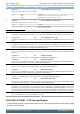
0 GLBLINTRMSK 0 RW Global Interrupt Mask (host and device)
The application uses this bit to mask or unmask the interrupt line assertion to itself. Irrespective of this bit's setting, the interrupt status
registers are updated by the core. Set to unmask.
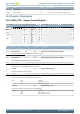
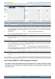
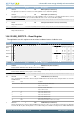
15.6.11 USB_GUSBCFG - USB Configuration Register
This register can be used to configure the core after power-on or a changing to Host mode or Device
mode. It contains USB and USB-PHY related configuration parameters. The application must program
this register before starting any transactions on either the AHB or the USB. Do not make changes to
this register after the initial programming.
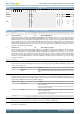
Offset Bit Position
0x3C00C
31
30
29
28
27
26
25
24
23
22
21
20
19
18
17
16
15
14
13
12
11
10
9
8
7
6
5
4
3
2
1
0
Reset
0
0
0
0
0
0x5
0
0
0
0x0
Access
W1
RW
RW
RW
RW
RW
RW
RW
RW
RW
Name
CORRUPTTXPKT
FORCEDEVMODE
FORCEHSTMODE
TXENDDELAY
TERMSELDLPULSE
USBTRDTIM
HNPCAP
SRPCAP
FSINTF
TOUTCAL
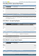
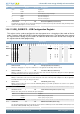
Bit Name Reset Access Description
31 CORRUPTTXPKT 0 W1 Corrupt Tx packet (host and device)
This bit is for debug purposes only. Never Set this bit to 1. The application should always write 0 to this bit.
30 FORCEDEVMODE 0 RW Force Device Mode (host and device)
Writing a 1 to this bit forces the core to device mode irrespective of the state of the ID pin. After setting the force bit, the application
must wait at least 25 ms before the change to take effect.
29 FORCEHSTMODE 0 RW Force Host Mode (host and device)
Writing a 1 to this bit forces the core to host mode irrespective of the state of the ID pin. After setting the force bit, the application
must wait at least 65 ms before the change to take effect.
28 TXENDDELAY 0 RW Tx End Delay (device only)
Writing 1 to this bit enables the core to follow the TxEndDelay timings as per UTMI+ specification 1.05 section 4.1.5 for opmode
signal during remote wakeup.
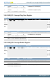
27:23 Reserved
To ensure compatibility with future devices, always write bits to 0. More information in Section 2.1 (p. 3)
22 TERMSELDLPULSE 0 RW TermSel DLine Pulsing Selection (device only)
This bit selects utmi_termselect to drive data line pulse during SRP.
Value Mode Description
0 TXVALID Data line pulsing using utmi_txvalid.
1 TERMSEL Data line pulsing using utmi_termsel.
21:14 Reserved
To ensure compatibility with future devices, always write bits to 0. More information in Section 2.1 (p. 3)
13:10 USBTRDTIM 0x5 RW USB Turnaround Time (device only)
Sets the turnaround time in PHY clocks. Specifies the response time For a MAC request to the Packet FIFO Controller (PFC) to fetch
data from the DFIFO (SPRAM). Always write this field to 5.