
User manual


...the world's most energy friendly microcontrollers
2012-04-24 - Giant Gecko Family - d0053_Rev0.96 329
www.energymicro.com
register) within 150 ms (TB_ACON_BSE0) of getting a USB_HPRT.PRTCONNDET
interrupt.
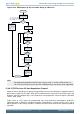
15.4.7 FIFO RAM Allocation
15.4.7.1 Data FIFO RAM Allocation
External RAM must be allocated among different FIFOs in the core before any transactions can start.
The application must follow this procedure every time it changes core FIFO RAM allocation.
The application must allocate data RAM per FIFO based on the AHB’s operating frequency, the PHY
Clock frequency, the available AHB bandwidth, and the performance required on the USB. Based on
the above mentioned criteria, the application must provide a table as described below with RAM sizes
for each FIFO in each mode.
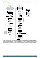
The core shares a single FIFO RAM between transmit FIFO(s) and receive FIFO.
In DMA mode—The FIFO RAM is also used for storing the some register information.
The Device mode Endpoint DMA address registers (USB_DIEP0DMAADDR, USB_DOEP0DMAADDR,
USB_DIEPx_DMAADDR, USB_DOEPx_DMAADDR) and Host mode Channel DMA registers
(USB_HCx_DMAADDR) are stored in the FIFO RAM.
• These register information are stored at the end of the FIFO RAM after the space allocated for receive
and Transmit FIFO. These register space must also be taken into account when calculating the total
FIFO depth of the core as explained in the following sections.
The registers USB_DIEPx_DMAADDR/USB_DOEPx_DMAADDR are maintained in RAM.
The following rules apply while calculating how much RAM space must be allocated to store these
registers.
Host Mode:
• Slave mode only: No space needed.
• DMA mode: One location per channel.
Device Mode:
• Slave mode only: No space needed.
• DMA mode: One location per end point direction.
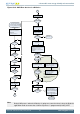
15.4.7.1.1 Device Mode
15.4.7.1.1.1 Tx FIFO Operation
When allocating data RAM for FIFOs in Device mode keep in mind these factors:
1. Receive FIFO RAM allocation:
• RAM for SETUP Packets: 4 * n + 6 locations must be Reserved in the receive FIFO to receive up
to n SETUP packets on control endpoints, where n is the number of control endpoints the device
core supports. The core does not use these locations, which are Reserved for SETUP packets,
to write any other data.
• One location for Global OUT NAK
• Status information is written to the FIFO along with each received packet. Therefore, a minimum
space of (Largest Packet Size / 4) + 1 must be allotted to receive packets. If a high-bandwidth
endpoint is enabled, or multiple isochronous endpoints are enabled, then at least two (Largest