
User manual

...the world's most energy friendly microcontrollers
2012-04-24 - Giant Gecko Family - d0053_Rev0.96 138
www.energymicro.com
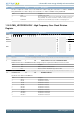
Bit Name Reset Access Description
Value Mode Description
0 8CYCLES Timeout period of 8 cycles
1 1KCYCLES Timeout period of 1024 cycles
2 16KCYCLES Timeout period of 16384 cycles
3 32KCYCLES Timeout period of 32768 cycles
17 LFXOBUFCUR 0 RW LFXO Boost Buffer Current
This value has been set during calibration and should not be changed.
16:14 HFCLKDIV 0x0 RW HFCLK Division
Use to divide HFCLK frequency by (HFCLKDIV + 1).
13 LFXOBOOST 0 RW LFXO Start-up Boost Current
Adjusts start-up boost current for LFXO.
Value Mode Description
0 70PCENT 70 % (default)
1 100PCENT 100 %
12:11 LFXOMODE 0x0 RW LFXO Mode
Set this to configure the external source for the LFXO. The oscillator setting takes effect when 1 is written to LFXOEN in
CMU_OSCENCMD. The oscillator setting is reset to default when 1 is written to LFXODIS in CMU_OSCENCMD.
Value Mode Description
0 XTAL 32.768 kHz crystal oscillator
1 BUFEXTCLK An AC coupled buffer is coupled in series with LFXTAL_N pin, suitable for external
sinus wave (32.768 kHz).
2 DIGEXTCLK Digital external clock on LFXTAL_N pin. Oscillator is effectively bypassed.
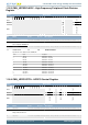
10:9 HFXOTIMEOUT 0x3 RW HFXO Timeout
Configures the start-up delay for HFXO.
Value Mode Description
0 8CYCLES Timeout period of 8 cycles
1 256CYCLES Timeout period of 256 cycles
2 1KCYCLES Timeout period of 1024 cycles
3 16KCYCLES Timeout period of 16384 cycles
8 Reserved
To ensure compatibility with future devices, always write bits to 0. More information in Section 2.1 (p. 3)
7 HFXOGLITCHDETEN 0 RW HFXO Glitch Detector Enable
This bit enables the glitch detector which is active as long as the start-up ripple-counter is counting. A detected glitch will reset the
ripple-counter effectively increasing the start-up time. Once the ripple-counter has timed-out, glitches will not be detected.
6:5 HFXOBUFCUR 0x1 RW HFXO Boost Buffer Current
The current level in the HFXO buffer should be set to default value when operating on 32 MHz or below. When operating on
frequencies above 32 MHz, the buffer current level should be set to 3.
Value Mode Description
1 BOOSTUPTO32MHZ Boost Buffer Current level when HFXO is below or equal to 32 MHz
3 BOOSTABOVE32MHZ Boost Buffer Current Level when HFXO is above 32 MHz
4 Reserved
To ensure compatibility with future devices, always write bits to 0. More information in Section 2.1 (p. 3)
3:2 HFXOBOOST 0x3 RW HFXO Start-up Boost Current
Used to adjust start-up boost current for HFXO.
Value Mode Description
0 50PCENT 50 %
1 70PCENT 70 %
2 80PCENT 80 %
3 100PCENT 100 % (default)
1:0 HFXOMODE 0x0 RW HFXO Mode