
User manual


...the world's most energy friendly microcontrollers
2012-04-24 - Giant Gecko Family - d0053_Rev0.96 101
www.energymicro.com
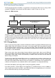
The BODs are constantly monitoring the voltages. Whenever the unregulated or regulated power drops
below the VBODthr value (see Electrical Characteristics for details), or if the AVDD0 or AVDD1 drops
below the voltage at the decouple pin (DEC), the corresponding active low BROWNOUTn line is held
low. The BODs also include hysteresis, which prevents instability in the corresponding BROWNOUTn
line when the supply is crossing the VBODthr limit or the AVDD bods drops below decouple pin (DEC).
The operation of the BOD is illustrated in Figure 9.3 (p. 101) . The “unknown” regions are handled
by the POR module.
Figure 9.3. RMU Brown-out Detector Operation
Unknown
BROWNOUTn
V
DD
time
V
Unknown
VBODthr
VBODhyst
VBODhyst
9.3.4 RESETn pin Reset
Forcing the RESETn pin low generates a reset of the EFM32GG. The RESETn pin includes an on-
chip pull-up resistor, and can therefore be left unconnected if no external reset source is needed. Also
connected to the RESETn line is a filter which prevents glitches from resetting the EFM32GG.
9.3.5 Watchdog Reset
The Watchdog circuit is a timer which (when enabled) must be cleared by software regularly. If software
does not clear it, a Watchdog reset is activated. This functionality provides recovery from a software
stalemate. Refer to the Watchdog section for specifications and description. A Watchdog reset does not
reset the Debug Interface. This allows an active debug session to continue in case of a Watchdog reset.
9.3.6 Lockup Reset
A Cortex-M3 lockup is the result of the core being locked up because of an unrecoverable exception
following the activation of the processor’s built-in system state protection hardware.
A Cortex-M3 lockup gives immediate indication of seriously errant kernel software. This is the result of
the core being locked up due to an unrecoverable exception following the activation of the processor’s
built in system state protection hardware. For more information about the Cortex-M3 lockup conditions
see the ARMv7-M Architecture Reference Manual. The Lockup reset does not reset the Debug Interface.
Set the LOCKUPRDIS bit in the RMU_CTRL register in order to disable this reset source.
9.3.7 System Reset Request
Software may initiate a reset (e.g. if it finds itself in a non-recoverable state). By asserting the
SYSRESETREQ in the Application Interrupt and Reset Control Register (write 0x05FA 0004), a reset is
issued. The SYSRESETREQ does not reset the Debug Interface.
9.3.8 EM4 Reset
Whenever EM4 is entered, the EM4RST bit is set. This bit enables the user to identify that the device
has been in EM4. Upon wake-up this bit should be cleared by software.