
- Silicon Laboratories, Inc. Radio User Manual


Si4734/35-B20
6 Rev. 1.0
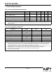
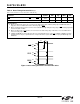
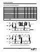
Figure 1. Reset Timing Parameters for Busmode Select
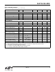
Table 4. Reset Timing Characteristics
1,2,3
(V
DD
= 2.7 to 5.5 V, V
IO
= 1.5 to 3.6 V, T
A
= –20 to 85 °C)
Parameter Symbol Min Typ Max Unit
RST
Pulse Width and GPO1, GPO2/INT Setup to RST↑
4
t
SRST
100 — — µs
GPO1, GPO2/INT
Hold from RST↑ t
HRST
30 — — ns
Important Notes:
1. When selecting 2-wire mode, the user must ensure that a 2-wire start condition (falling edge of SDIO while SCLK is
high) does not occur within 300 ns before the rising edge of RST.
2. When selecting 2-wire mode, the user must ensure that SCLK is high during the rising edge of RST
, and stays high until
after the first start condition.
3. When selecting 3-wire or SPI modes, the user must ensure that a rising edge of SCLK does not occur within 300 ns
before the rising edge of RST
.
4. If GPO1 and GPO2 are actively driven by the user, then minimum t
SRST
is only 30 ns. If GPO1 or GPO2 is hi-Z, then
minimum t
SRST
is 100 µs, to provide time for on-chip 1 MΩ devices (active while RST is low) to pull GPO1 high and
GPO2 low.
70%
30%
GPO1
70%
30%
GPO2/
INT
70%
30%
t
SRST
RST
t
HRST