
User`s guide


C8051F34x-DK
Rev. 0.1 9
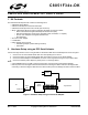
7.1. System Clock Sources
The
C8051F340
device installed on the target board features a calibrated programmable internal oscillator which is
enabled as the system clock source on reset. After reset, the internal oscillator operates at a frequency of 1.5 MHz
(±1.5%) by default but may be configured by software to operate at other frequencies. Therefore, in many applica-
tions an external oscillator is not required. However, if you wish to operate the C8051F340 device at a frequency not
available with the internal oscillator, an external crystal may be used. Refer to the
C8051F34x
datasheet for more
information on configuring the system clock source.
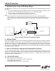
The target board is designed to facilitate the installation of an external crystal. Remove shorting blocks at headers
J10 and J11 and install the crystal at the pads marked Y1. Install a 10 MΩ resistor at R1 and install capacitors at C6
and C7 using values appropriate for the crystal you select. Refer to the C8051F34x datasheet for more information
on the use of external oscillators.
7.2. Switches and LEDs
Three switches are provided on the target board. Switch RESET is connected to the RESET pin of the C8051F340.
Pressing RESET puts the device into its hardware-reset state. Switches P2.0 and P2.1 are connected to the
C8051F340’s general purpose I/O (GPIO) pins through headers. Pressing P2.0 or P2.1 generates a logic low sig-
nal on the port pin. Remove the shorting blocks from the J12 header to disconnect Switch P2.0 and Switch P2.1
from the port pins. The port pin signals are also routed to pins on the J1 I/O connector. See Table 1 for the port pins
and headers corresponding to each switch.
Three LEDs are also provided on the target board. The red LED labeled PWR LED is used to indicate a power con-
nection to the target board. The green surface-mount LEDs labeled with port pin names areconnected to the
C8051F340’s GPIO pins through headers. Remove the shorting blocks from the header to disconnect the LEDs
from the port pin. The port pin signals are also routed to pins on the J1 I/O connector. See Table 1 for the port pins
and headers corresponding to each LED.
Also included on the C8051F340 target board is a 10 K
Ω
Thumb-wheel Rotary Potentiometer, part number R10. The
Potentiometer is connected to the C8051F340’s P2.5 pin through the J17 header. Remove the shorting block from
the header to disconnect the Potentiometer from the port pin. The port pin signal is also routed to a pin on the J1 I/O
connector. See Table 1 for the port pin and header corresponding to the Potentiometer.
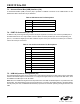
Table 1. Target Board I/O Descriptions
Description I/O Header
SW1 Reset none
SW2 P2.0 J12[1-2]
SW3 P2.1 J12[3-4]
Green LED P2.2 J12[5-6]
Green LED P2.3 J12[7-8]
Red LED PWR none
Potentiometer P2.5 J17