
User`s guide


C8051F34x-DK
Rev. 0.1 13
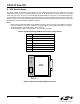
9. USB Debug Adapter
The USB Debug Adapter provides the interface between the PC’s USB port and the C8051F34x’s in-system
debug/programming circuitry. The attached 10-pin DEBUG ribbon cable connects the adapter to the target board
and the target device’s debug interface signals. (The USB Debug Adapter supports both Silicon Laboratories JTAG
and C2 debug interfaces.) Power is provided to the adapter from the USB connection to the PC. The USB Debug
Adapter is capable of providing power to a circuit board via pin 10 of the DEBUG connector. See Section 7.9. for
instructions on powering the C8051F340 target board from this source. Table 7 shows the pin definitions for the
DEBUG ribbon cable connector.
Notes:
• The USB Debug Adapter requires a target system clock of 32 KHz or greater.
• With the default settings, the USB Debug Adapter can supply up to 100 mA to a target system.
Figure 6. USB Debug Adapter
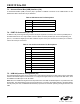
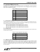
Table 7. USB Debug Adapter DEBUG Connector Pin Descriptions
Pin # Description
1,8 Not Connected
2,3,9 GND (Ground)
4TCK (C2D)
5TMS
6TDO
7TDI (C2CK)
10 USB Power