
User`s guide


C8051F34x-DK
12 Rev. 0.1
8. EC2 Serial Adapter
The Serial Adapter provides the interface between the PC’s RS232 serial port and the C8051F34x’s in-system
debug/programming circuitry. The Serial Adapter connects to the C8051F340 C2 debug interface on the target
board using the 10-pin connector on the Serial Adapter labeled “DEBUG”, see Figure 5. (The Serial Adapter sup-
ports both Silicon Laboratories JTAG and C2 debug interfaces.). All Serial Adapters may be powered from the tar-
get board, but the EC1 and EC2 Serial Adapter units cannot provide power to the target board. Table 6 shows the
pin definitions for the Serial Adapter’s DEBUG connector.
Notes:
• When powering the Serial Adapter via the DEBUG connector, the input voltage to the DEBUG connector’s
power pin must be 3.0 to 3.6 VDC. Otherwise, the Serial Adapter must be powered directly by connecting
the AC/DC adapter to the Serial Adapter’s DC power jack.
• The Serial Adapter requires a target system clock of 32 KHz or greater.
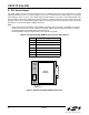
Figure 5. EC2 Serial Adapter DEBUG Connector
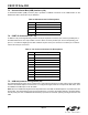
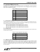
Table 6. EC2 Serial Adapter DEBUG Connector Pin Descriptions
Pin # Description
1 3.0 to 3.6 VDC Input
2,3,9 GND (Ground)
4TCK (C2D)
5TMS
6TDO
7TDI (C2CK)
8,10 Not Connected
Pin 1
Serial
Adapter
Pin 2
DEBUG
Pwr
Run/
Stop
RS232