
User`s guide


C8051F34x-DK
10 Rev. 0.1
7.3. Universal Serial Bus (USB) Interface (J14)
A Universal Serial Bus (USB) connector (P3) is provided to facilitate connections to the USB interface on the
C8051F340. Table 2 shows the J14 pin definitions.
7.4. PORT I/O Connectors (J2 - J6)
In addition to all port I/O signals being routed to the 96-pin expansion connector, each of the five parallel ports of
the C8051F340 has its own 10-pin header connector. Each connector provides a pin for the corresponding port
pins 0-7, +3.3 VDC and digital ground. Table 3 defines the pins for the port connectors. The same pin-out order is
used for all of the port connectors.
7.5. USB Self-powered Configuration (J8)
The C8051F340 target board can be configured as a self-powered USB device to take power from the USB cable
instead of the AC/DC adapter connected at P1. To configure the target boards as a self-powered USB device, short
the VREGIN and VBUS pins on the J8 header
Note: When the C8051F340 target board is self-powered from the USB, the Serial Adapter is not powered from the
target board. The Serial Adapter must be powered directly by connecting the AC/DC adapter to the Serial Adapt-
ers’ DC power jack. Also, the RS232 Serial Interface (P4) cannot be used when powering the target board from the
USB.
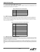
Table 2. USB Connector Pin Descriptions
Pin # Description
1 VBUS
2D-
3D+
4 GND (Ground)
Table 3. J12–J19 Port Connector Pin Descriptions
Pin # Description
1Pn.0
2Pn.1
3Pn.2
4Pn.3
5Pn.4
6Pn.5
7Pn.6
8Pn.7
9 +3VD (+3.3VDC)
10 GND (Ground)