
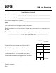
User`s guide
The C8051F040 still has a UART0 serial port for printing output or debugging information on a terminal. As in all
MPS labs the port must be configured with a counter to set the BAUD rate. The C8051F040 does not have a PLL
so the crystal oscillator frequencies are greatly limited. After initialization switch to the 22.1184MHz crystal
frequency to reduce confusion and keep the setup option simple.
USAGE GUIDELINES AND INSTRUCTIONS
1. Safety
a. While the voltages used in this project are not dangerous, there may be a danger of damage to the
hardware due to excessive current flow. It is necessary to always connect this device to a power supply
that limits current to a safe level. Unsafe power supplies include devices such as car batteries.
b. Do not short any connectors as damage or fire may result.
c. Always verify that the drive wheels are off the ground before attempting to start the car’s motor. Also
ensure that the front wheels are free to turn.
2. Initial Setup / Components Identification.
a. It is necessary to supply only +5V power and ground to the car unit. Identify the 2 twisted-pair power
cables from the car. It has a red and a black plug, and the red plug is labeled with a voltage. The black plug
corresponds to the ground.
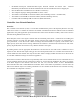
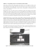
b. There are 3 DB-9 connectors on the CAN bus cable. The two male connectors have the correct pin-out to
interface to the C8051F040 development boards in the lab. The female connector follows OBD-II standard
pin-outs and is suitable for connection to certain other commercially available CAN devices. There are
various CAN cables with both male and female DB-9 connectors as well as splitter and multi-tap cables.
There are enough cable types to handle the worst-case configuration: 2 8051s, the car, and 2 PCs running
LabVIEW all connected on the CAN bus simultaneously. It should be noted that the 2 NI CAN cables with
female DB-9 connecter have terminating resistors on the end with the label. The CAN bus specifications
call for terminating resistors at both far ends of the physical bus. The car also has built-in terminating
resistors.
CAUTION: when attaching several devices to the CAN bus simultaneously make sure the bus isn’t
flooded with commands. The relatively slow bus configuration used here can only handle a limited
number of commands per second.
c. The order of power supply power-up sequencing is unimportant, but it is important to check all power
connections for correct voltage and polarity before turning on power.
3. Use of CAN Interface
a. 11-bit CAN message IDs are used for all communication.
b. The CAN interface on the car will receive messages with several message IDs. (See Appendix A.)
c. The CAN interface on the car transmits several messages with real-time data from sensors. (See Appendix
A.)
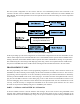
d. The C8051F040 development boards need to be plugged into the Control and Meter Modules to correctly
send and receive CAN information. Each 10-pin connector should be placed on the pins such that pin 1 of
the connector aligns with pin 1 of the port (except for the DAC - see 2b in Appendix B). This corresponds
to having the end of the connector with the ribbon on it facing the side that the power to the board comes
in on.