
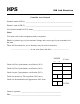
User`s guide

PART III - C Programming: Separate Control Module and Meter Module
In this portion of the lab, write a simple program which will turn on the car’s headlights by sending a CAN
message containing the bytes 0x0001 with ID 0x01. This will require use of the can_init( ), can_get_tx_buf( ),
can_set_address_std( ), can_set_buffer_data( ), can_send_tx_buf( ), and can_send_rtr( ) functions. You may also
wish to test CAN message reception using the can_get_rx_msg( ), can_get_address( ), can_get_data_byte( ), and
can_free_rx_msg( ) functions.
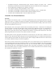
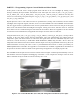
Expand upon the code to read values from the two potentiometers (steering and acceleration) and the switches
(headlights, left & right turn signals, and horn) on the car Control Module. The Control Module is the black box
with two toggle switches, a push-button switch, and two potentiometers, shown in the lower left part of the figure
below. Your code should control the headlights, turn signals, steering, drive motor, and horn on the car. Transmit
these values to the car’s CAN bus using the same functions used in Part I. Please see Appendix A for the CAN IDs
to be used for each controlled item, and appendix B for the pin-out of the control’s connectors.
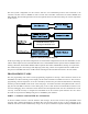
Using the functions can_init( ), can_get_rx_msg( ), can_get_address( ), and can_get_data_byte( ), develop code for
the 8051 to drive the analog meters and turn signal LEDs. Your code should display the readings from the
temperature, speed, and current sensors as well as the turn signal status. Since the C8051F040 only has 2 D/A
converters, it will be necessary to enable Pulse Width Modulation (PWM) using the 8051’s PCA to drive the
temperature meter. Please see the 8051 reference manual, chapter 24 on the programmable counter array (PCA) for
further information. You may also want to refer to your Embedded Control notes to refresh your memory for
PWM implementation on the 8051. See Appendix A for information on CAN IDs, Appendix B for information on
the pin-out for the meters and more details on all signal wiring and Appendix C for sample program code.
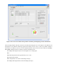
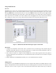
The LabVIEW VI developed for Part I with the features shown in Figure 5 should respond identically to the car
and should be used in development and debugging of the 8051 C code. Compare the messages in the VI viewer
buffer commands sent by the sender VI to those issued by the C code.
Figure 6: Car Control Module Box (lower left) and Analog Meter Module Box (lower right).