
User`s guide
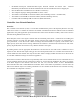
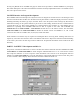
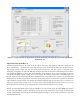
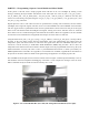
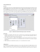

Figure 5: A typical student-developed front panel for monitoring and displaying all CAN bus information
from the RC car.
Important Notes on the RC Car
All the functions on the car work, however the drive motor may cause some problems. The input voltage must be
above a threshold of ~1.3V before the wheels will turn, and even at that the wheels will need to be kick-started. A
high enough starting voltage will start the wheels without a kick-start. The drive motor is extremely noisy,
electrically, and attempts to reduce the EMI have not been successful. If the motor is left running for more than a
few seconds the EMI may crash the PIC microcontroller. If that happens, the car stops responding to all CAN
commands and must be reset by cycling the 5V power supply. This is inconvenient, but not insurmountable as to
prevent the lab exercise from being completed. Another known issue is with the drive transistor for the inductively
loaded motor. Even with a bypass diode, if the base current to the transistor is turned off too quickly the transistor
will breakdown and pass current even though the transistor should be shut off. The best way to avoid this is to
ramp down the base current slowly (over ~1 second). If the motor still runs when the base current is off you can
always shut off the +5V to the car or bring up the base current again and ramp down more slowly.
The RC car will automatically send a message with ID 8 every few seconds giving the wheel RPM value. This is
the only data sent without a request command. To get the status of the temperature, motor current, and turn signals
a CAN command must be send with the desired ID and the RTR flag set (in the sender VI panel or in the CAN
command function call).