
User`s guide
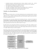
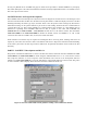
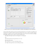
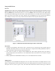

Figure 4: The CAN-viewer-MPS.vi front panel for monitoring and displaying CAN bus information.
After becoming familiar with both of these VIs and their block diagrams, one of the objectives of PART II is the
development of an enhanced monitoring program that displays the rest of the car data. On possible example is
shown below. In addition to the list of CAN commands passed on the bus and the three indicators (Headlight,
Wheel RPM, and Motor Current), students are asked to add indicators for:
Left & Right Turn Signals (may be activated together as a warning light)
Horn
Wheel Steering Position (from approximately -20° to +20°)
Drive Motor Input Voltage
Motor Temperature in °C (from a Status Reply message)
Left & Right Turn Signal Status (from a Status Reply message)